0
\$\begingroup\$

Several days ago I asked about this question: How to construct a propeller clock in Unity? But I don't understand how the answer works.

I have 0 knowledge about shaders, so I picked up a tutorial to understand the math functions, but that still didn't helping much in understanding the code.

I cut off part of the code to check the effect on an image, and I want to understand why the code has this effect.

  1. What is the range of values for the parameters i.uv.y or i.uv.x?

  2. Next I discarded part of the code, simplifying the fragment shader to just:

    fixed4 frag (v2f i) : SV_Target
    {
        // Simulate the strip of LEDs spinning around very fast.
        float headAngle = _Time.y ;
    
        // Compute the angle of the pixel we're rendering.
        float angle = atan2(i.uv.y, i.uv.x);
    
        float difference = frac( angle / (2.0f * 3.141592653589f));
    
        return difference;
    }
    

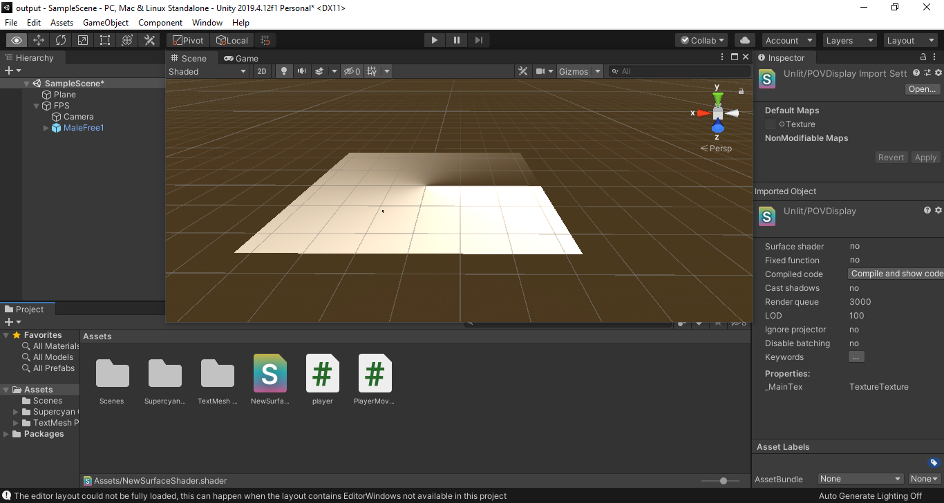
    And I rendered this on a plane:

    Angular gradient

    According to the documentation, atan2 gives an angle value in between -pi and pi. So the range of angle / (2.0f * 3.141592653589f)) is in between -0.5 and 0.5.

    I tested with frac(0.3), frac(0.25), which is the same as return 0.3 or return 0.25 since frac preserves only the decimal number. But why I couldn't generate the same gradient image as the one above? Instead, the plane is all one shade of grey, no matter what number I use.

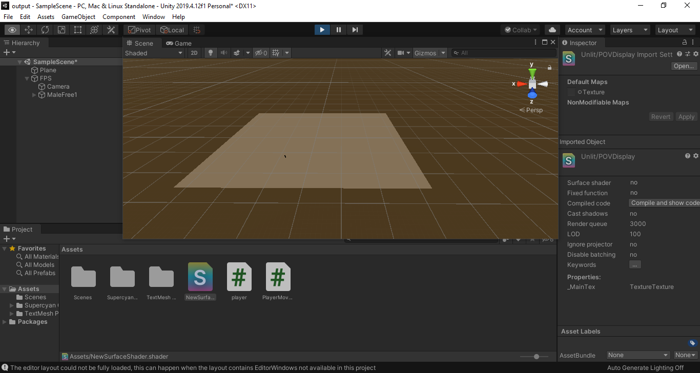
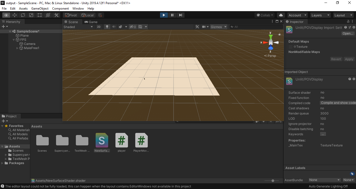
  3. Next I tried the code float difference = frac(headAngle) and got an image which is constantly varying between dark and bright images like these:

    Dark plane Light plane

  4. Putting this together:

    • From the 1st picture, I have an image with a gradient that's dark in the 1st quadrant and bright in the 4th quadrant.

    • From the 2nd & 3rd pictures, I have all four quadrants at the same brightness, constantly varying between them.

    What I don't understand is how the sum of these two pieces of code works. If I combine them like this:

    float difference = frac(headAngle + angle / (2.0f * 3.141592653589f));
    

    Shouldn't I get a gradient that stays in one place, like the 1st image, but just changes in brightness like in images 2 & 3?

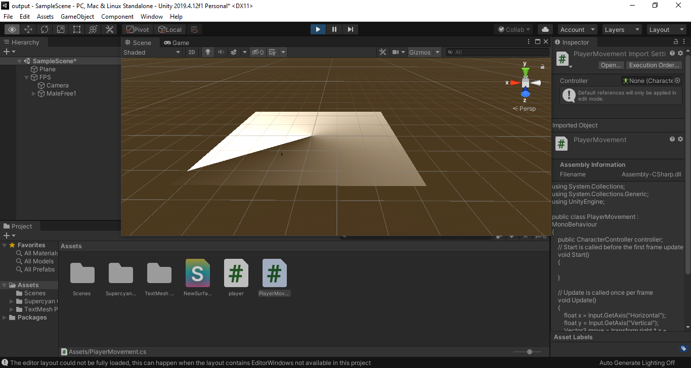
    Instead I get a A brightness gradient that is sweeping in a circle around the plane:

    Sweeping gradient

    ...and I don't understand why.

\$\endgroup\$
1
  • \$\begingroup\$ UV values are typically between [0, 1] for most models. You can go well outside that range if you want to, but this is usually only done for packing special information into UV channels. In your case I would expect [0, 1] since this is just the default plane or quad model. Although it looks like you shift the range in your vertex function to [-1, 1] \$\endgroup\$ Commented Jan 29, 2021 at 7:33

1 Answer 1

1
\$\begingroup\$
  1. What is the range of values for the parameters i.uv.y or i.uv.x?

Usually a quad's texture coordinates will run from 0 to 1 on the u (x) axis, and 0 to 1 on the v (y) axis.

That matches the normalized sampling coordinates we use for looking up into a texture:

  • (0, 0) = bottom left
  • (1, 1) = top right

(In some contexts, 0 is the top instead of the bottom, but let's call it the bottom here for simplicity)

But in this code, you can see I remap the range inside the vertex shader:

v2f vert (appdata v)
{
     v2f o;
     o.vertex = UnityObjectToClipPos(v.vertex);
     // Shift our texture coordinates so 0 is in the center,
     // and we go to -1 ... +1 at the edges.
     o.uv = (v.uv - 0.5f) * 2.0f;
     return o;
}

This output structure o gets interpolated for each pixel in the triangle formed by three vertices, and those interpolated versions get passed to the fragment shader as the input structure i.

By subtracting 0.5, I ensure the middle of the quad becomes the origin (0, 0). Then by scaling by 2, I ensure a circle with radius 1 centered at the origin exactly touches the edges of the quad.

Then in the fragment shader, we convert the texture coordinates of the pixel we're drawing into polar coordinates. This code gives us the angle of our pixel around the center of the quad, measured counter-clockwise from the positive u (x) axis.

// Compute the angle of the pixel we're rendering.
float angle = atan2(i.uv.y, i.uv.x);

That's why, when you plot this value as a greyscale colour, you get a gradient that gets brighter as you look around the quad in a counter-clockwise direction - that's the measured angle to this pixel.

As you reasoned, since the range of atan2 is from \$-\pi\$ to \$\pi\$, dividing this by \$2 \pi\$ gives us a range from -0.5 to 0.5. The frac function then takes the negative values and wraps them around to positive. We can visualize this as a graph in the angular domain:

Graphs of angle/2pi and frac(angle/2pi)

So here we have a function that varies over space with the angle of the pixel - from 0 (black) at the start of quadrant I to 1 (white) at the end of quadrant IV. But it doesn't vary over time.

The next bit of code you tried does the opposite: it varies over time, but it doesn't vary across space.

float headAngle = _Time.y;
float difference = frac(headAngle)

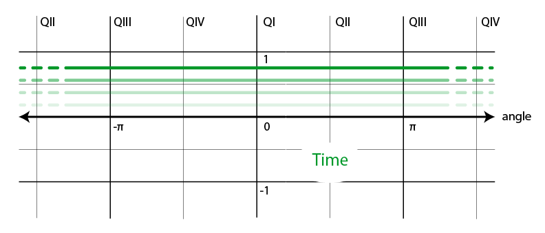
_Time is a built-in variable that Unity populates with various different scaled measures of the time elapsed in the game (the y component happened to contain a convenient scale for the effect I was making). So its value constantly increases from one frame to the next. But within a single frame, it's a constant - no matter what pixel looks up _Time.y, they'll all get the same value. That makes a graph that looks like this:

Graph of horizontal line for time. Ghosted lines indicate the level is rising.

Here I've visualized multiple consecutive frames. You can see in any one frame, _Time.y is a constant, horizontal line in this graph: it's the same at any angle. But from one frame to the next that line rises. Eventually it hits the top of the frac range and wraps back down to zero, then rises again.

Now we're ready to put these two pieces together. Let's take our red plot of frac(angle/(2*pi)) we had before, and imagine what happens when we add this lifting influence of time to it:

Graphs of frac(angle/(2pi)) + Time and frac(angle/(2pi) + Time)

Increasing the time offset lifts the whole graph up. But then frac cuts off any parts that go above 1 and wraps them back around to the bottom.

Each time we lift the line, more of the right (counter-clockwise) side of it goes above 1, so we trim that part off and move it down to zero. Which means that effectively the peak value of the graph moves to the left (clockwise) as time goes on.

That's what makes our radar-like gradient sweep around the circle.

\$\endgroup\$
2
  • \$\begingroup\$ I see float angle = atan2(i.uv.y, i.uv.x) return a range of values in between -pi and pi and not a specific value within this range that is why I couldn't generate a brightness gradient by testing return frac(0.3),frac(0.2) and etc. The graph is helpful in understanding why at the first quadrant there a significant brightness difference along x axis in 1st and 4th quadrant(brightness actually increase from 0 rad to 2pi rad). Finally able to understand these part😄 \$\endgroup\$
    – chuackt
    Commented Jan 29, 2021 at 22:50
  • \$\begingroup\$ It does return a specific value in that range, for each input. It's just that as you vary the input x and y (over the surface of the quad), you also vary the output. \$\endgroup\$
    – DMGregory
    Commented Jan 29, 2021 at 22:56

You must log in to answer this question.

Not the answer you're looking for? Browse other questions tagged .