0
\$\begingroup\$

I am considering the possibility of using Unity to construct a propeller clock like this one (also called a persistence of vision or POV display).

It's an array of LEDs on a PCB board connected to motor that spins at a high RPM. The LEDS flash on and off such that it generates the appearance of a clock face.

So far, I've tried turning a red pointer in a circular path with high RPM in Unity, but I don't get an image of a circular red disc. Instead I see a pointer showing random discrete movement in a circular path.

Is there any suggestion to rectify this issue?

\$\endgroup\$
6
  • 1
    \$\begingroup\$ Are you trying to simulate the resulting visuals of a propeller clock or are you trying to build a physics type simulation? In game dev it is common to focus on the results (in particular the 'feel' of the results) rather than building a digital replica of some real world situation. The paths toward simulating the output of a system often differ from simulating the entire system directly. \$\endgroup\$
    – Pikalek
    Commented Jan 23, 2021 at 16:40
  • \$\begingroup\$ The feel will be sufficient even by mean of other method in unity. \$\endgroup\$
    – chuackt
    Commented Jan 23, 2021 at 16:51
  • \$\begingroup\$ Sounds like a pretty advanced lighting technique. I believe you can do this with the HDRP pipeline but I have never directly tested this. When using HDRP (I use it for AR projects) one issue I often have is unity lights can leave behind light trails when moving at high speeds. For me this is not the desired effect since it can happen at pretty low speeds, so I normally turn off the feature, for you, this is probably exactly what you want. Using HDRP (you may need fog and bloom post processing as well) you should be able to get an effect similar to your goal but... \$\endgroup\$ Commented Jan 23, 2021 at 17:55
  • \$\begingroup\$ It probably wont look quite right, most likely due to update times. Obviously a PCB board and chips are way faster than the Unity renderer, so your motion trail will probably look pretty pixelated unless the propeller is big enough where update times don't really matter. I'm not sure you could use this for a proper game, but I'm willing to bet with enough hacking around you could probably make an okay testing simulation. Your other more light weight but code heavy option would be to try and use a feedback effect: github.com/keijiro/KinoFeedback \$\endgroup\$ Commented Jan 23, 2021 at 17:57
  • \$\begingroup\$ This type of clock is called a Persistence of Vision Display (POV). It uses the fact that when our eyes see a bright point of light for an instant, we continue to perceive a glow in that spot of our visual field for a fraction of a second afterward - long enough for the propeller to spin back around and refresh the image. It also uses the fact that real time is continuous - light an LED for a period of time, and it will sweep an illuminated arc, not just a single point. Unity won't simulate either effect by default - it takes discrete snapshots with no persistence - but you can change that. \$\endgroup\$
    – DMGregory
    Commented Jan 23, 2021 at 18:23

1 Answer 1

5
\$\begingroup\$

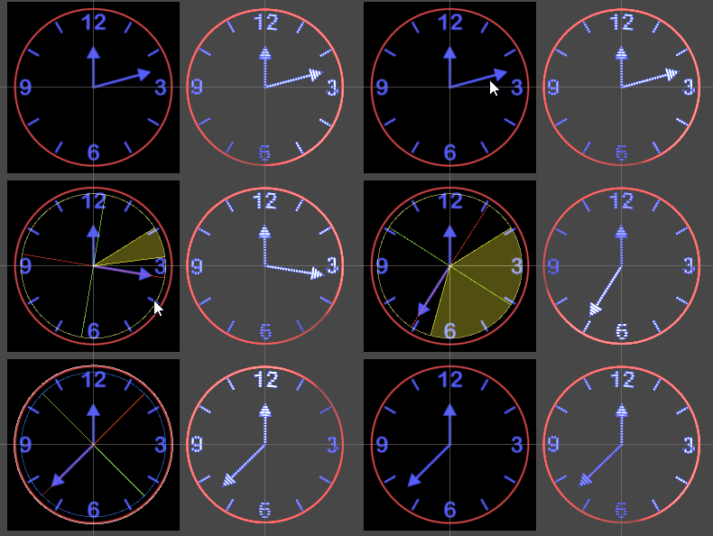
Here's an example of how we can mimic this appearance in a Unity scene:
Example POV Display

My strategy is:

  1. First, compose the image that the POV display is trying to project.

  2. Render that image, with a shader filter that adds artifacts that look like a POV display.

On the left is step 1. I've positioned some sprites representing my clock face and hands. That way it's easy to update the displayed image: I can just rotate the game objects representing the hands.

I created a new RenderTexture in my assets folder, called "Clock Face". Because the POV display is quite low-res, you can get away with a tiny texture here.

Next I made a Camera that looks at these sprites, and outputs the combined image to the RenderTexture. You can put the sprites in a layer that only that camera sees, so they're invisible to your main scene camera.

Lastly I made a quad to display the POV version. I gave that quad a new material, with a custom shader, using the RenderTexture as its Main Texture input.

Here's the shader I cooked up:

Shader "Unlit/POVDisplay"
{
    Properties
    {
        _MainTex ("Texture", 2D) = "white" {}
    }
    SubShader
    {
        // Render with transparent objects, after the opaque pass.
        Tags { "RenderType"="Transparent" "Queue"="Transparent"}
        LOD 100

        // Don't write to the depth buffer.
        ZWrite Off
        // Additive blending (add light/glow).
        Blend One One

        Pass
        {
            CGPROGRAM
            #pragma vertex vert
            #pragma fragment frag

            #include "UnityCG.cginc"


            struct appdata
            {
                float4 vertex : POSITION;
                float2 uv : TEXCOORD0;
            };

            struct v2f
            {
                float2 uv : TEXCOORD0;
                float4 vertex : SV_POSITION;
            };

            sampler2D _MainTex;
            float4 _MainTex_ST;

            v2f vert (appdata v)
            {
                v2f o;
                o.vertex = UnityObjectToClipPos(v.vertex);
                // Shift our texture coordinates so 0 is in the center,
                // and we go to -1 ... +1 at the edges.
                o.uv = (v.uv - 0.5f) * 2.0f;
                return o;
            }

            fixed4 frag (v2f i) : SV_Target
            {
                // Vary this parameter to control how many rings of light you get.
                const float ledCount = 32;
                                
                // Simulate the strip of LEDs spinning around very fast.
                float headAngle = _Time.y * 7.0f;

                // Compute the angle of the pixel we're rendering.
                float angle = atan2(i.uv.y, i.uv.x);
                
                // Compute how recently we've been illuminated.
                // 0 = head is about to reach us (1 full cycle behind).
                // 1 = head just reached us.
                float difference = frac(headAngle + angle / (2.0f * 3.141592653589f));

                // The approaching LED head shines light on the faded parts nearby,
                // so brighten them back up to 1.
                if (difference < 0.1f)
                    difference = 1.0f - 9.0f * difference;

                // Small timing errors make the display seem to twist/wobble,
                // so we'll distort our angle a bit to mimic this.
                angle += 0.01f * sin(_Time.y * 2.0f + difference * 1.0f);

                // Compute our radius in "LED space"
                float radius = length(i.uv) * ledCount;

                // Round to the nearest LED.
                float rounded = round(radius);

                // Compute a sample point in our texture, using our distorted angle
                // and rounded radius.
                float2 samplePoint = float2(cos(angle), sin(angle))*rounded/ledCount;               
                
                // Sample the RenderTexture at this position.
                fixed4 col = tex2D(_MainTex, samplePoint / (2.0f) + 0.5f);
                // Square the colour to increase saturation, like a pure LED light.
                col *= col;

                // The center of the LED is brighter. Fade it in the gaps between rings.
                float brightness = (radius - rounded) * 2.0f;
                brightness = 1.0f - brightness * brightness;
                
                // Brighten/darken the colour based on proximity to the ring,
                // and lag behind the spinning head.
                return col * brightness * lerp(9.0f, 1.0f, difference);
            }
            ENDCG
        }
    }
}

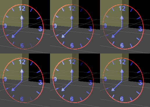
If we scale down our _Time.y input, we can see what this looks like in slow-mo:
Slow POV Clock

Advancing our virtual "LED Head" faster than the display framerate makes the brightest part of the sweep jump around almost randomly, giving that distinctive flickering appearance.

\$\endgroup\$
5
  • \$\begingroup\$ Thanks for your enthusiasm!! This is amazing. Been studying the code, can you explain more details regarding this line? "float difference = frac(headAngle + angle / (2.0f * 3.141592653589f))" . The value of "angle" can be in between -pi to pi if I understand correctly and "headAngle" is float number which is 7f*time and frac() is to get the decimal number only and you commented 0=head about to reach us,1=head just reached us, I still don't catch it, what the comment suppose to mean, can elaborate more? \$\endgroup\$
    – chuackt
    Commented Jan 26, 2021 at 17:06
  • \$\begingroup\$ angle divided by two pi gives us a value beween -0.5 and 0.5. Add a large positive number to it and its fractional component will vary between 0 and 1. That creates a dark-to-light gradient wrapping around our image. Adding headAngle as an offset shifts this gradient, so it sweeps around the disc. When in doubt, try adding a return line to output the quantity you're curious about, like return difference; and that will show you exactly where it's high/low. \$\endgroup\$
    – DMGregory
    Commented Jan 26, 2021 at 17:14
  • \$\begingroup\$ Ok I guess I have no talent in this, been learning tutorial about shader the whole day yet do not have the faintest idea what going on here🤣. Just to satisfy my curiosity, what the value return by i.uv.y or i.uv.x as I tried return angle=atan2(1,2) and etc i couldn't generate the dark to light gradient image. Also tried return difference=frac(headangle), got an image varying between dark and white, return difference=frac(angle/2pi), got a constant image that is darken at the 1st quadrant. \$\endgroup\$
    – chuackt
    Commented Jan 28, 2021 at 3:58
  • \$\begingroup\$ how does the sum of these 2 effect generate a sweep across the disc? Most likely I on the wrong direction. \$\endgroup\$
    – chuackt
    Commented Jan 28, 2021 at 3:59
  • \$\begingroup\$ Let's discuss this in Game Development Chat tomorrow. It's too much to fit in a comment here. Or you could post it as a separate question. \$\endgroup\$
    – DMGregory
    Commented Jan 28, 2021 at 4:01

You must log in to answer this question.

Not the answer you're looking for? Browse other questions tagged .