Inside the GPU pipeline, each vertex represents a unique combination of:
a position (so we know where to draw this corner of the adjacent polygon(s) on the screen)
a normal vector (which way the surface is facing at this point, so we can light & shade the attached polygons accordingly)
texture coordinates (so we know which part of the texture to sample for this part of the surface)
If multiple polygons share one of these GPU vertices, they share all of the above. That means:
shared position: the polygons will meet at exactly the same corner. When both vertices along an edge are shared in this way, the result is a "watertight" join between the polygons, with no crack or gap in-between them.
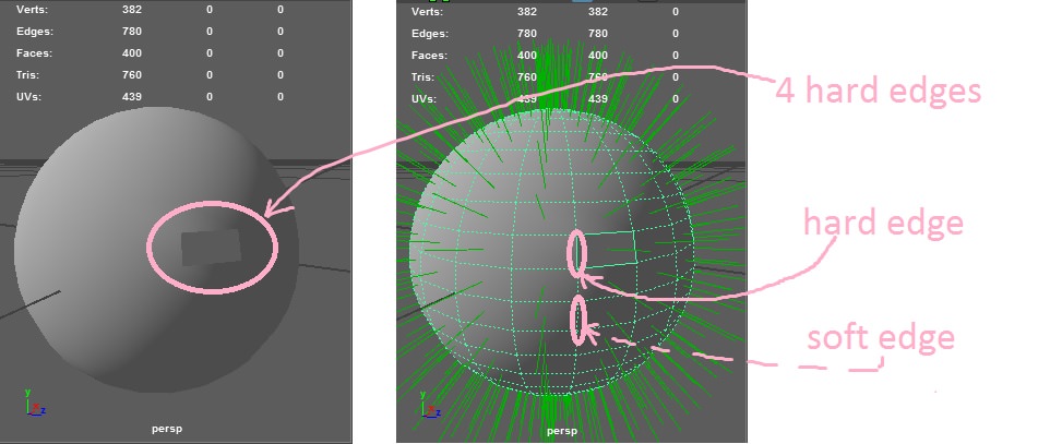
shared normal: the polygons will have the same shading at this corner. When both vertices along an edge are shared in this way, the result is a "smooth" edge, where the lighting is flat or a smooth gradient across the edge, rather than a "hard edge" that shows a sharp crease between darker and lighter shaded polygons.
shared texture coordinates: the polygons will reference the same part of the texture at this corner. When both vertices along an edge are shared in this way, the texture will wrap continuously across this edge, with no discontinuity or "seam" where different parts of the texture butt up against each other.
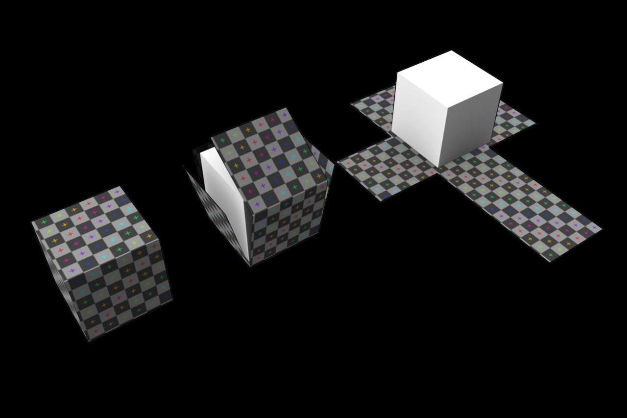
We don't always want all of the above though. Consider this image of a texture mapped cube by Zephyris, via Wikipedia:

Here we can see as we unwrap the cube onto the flat plane of texture space, we have to cut it along certain edges (making a "net" we can unfold flat). Some faces of the cube that meet at the same place in 3D space end up sitting in very different parts of the flattened texture space (like the two far edges of the cross). That's a texture discontinuity, called a "seam" (by analogy with sewing, where to make this cube out of a sheet of fabric, we'd have to stitch-together these cut edges).
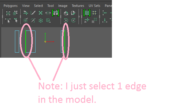
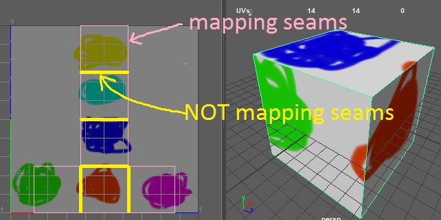
In 3D modelling software, the vertices on both sides of a texture seam corner are commonly still counted as "one" vertex, that just happens to have different texture coordinates associated with it on each face. When exporting to a game's GPU pipeline though, these vertices get split into separate copies: one with the texture coordinates for the faces on one side of the seam, one with the texture coordinates for the faces on the other side of the seam (and the other, and the other, for vertices at the meeting point of several seams)
This has a slight overhead, since it's increasing the vertex count of the model, meaning more data to transfer to the GPU and process when rendering. So that's why you'll find some guides recommending to minimize cases where you need to split vertices in this way. Avoiding unnecessary seams also helps when painting the texture, as it cuts down on places where the artist needs to match the texture on one edge to that on another edge elsewhere in the texture to avoid visible seams, or where mipmapping can cause unwanted colour leaks.
The same thing happens wherever we want a "hard" edge, where the shading changes sharply On the cube above, all six faces point in different directions, with hard edges in between. So we'd need to split every corner vertex to provide a different normal vector for each of the three faces that meet there. So in the 3D modelling program it might look like we have 8 vertices, but we actually end up sending 24 down the rendering pipeline.
This overhead is quite minor compared to other costs in the rendering pipeline, so it's not something you need to go out of your way to avoid entirely. Every textured 3D object that isn't just a mostly-flat sheet will need a texture seam somewhere, so it's usually just a matter of choosing where to put it to make your texture artists' lives easier. ;)


