2
\$\begingroup\$

Edit: Currently, I am looking for a method which will allow a player to control a 2D mesh and navigate along the surface of a 3D mesh. Visually, this would look like the player is inhabiting a 2D world. This 2D world would be the "wallpaper" (the surface) of a 3D object.

I've been trying to solve this problem by implementing a solution which can do realtime UV mapping of vertices. Note, however, that this may not be the best or even proper solution to this problem and any alternatives which better solve the aforementioned problem are welcome.

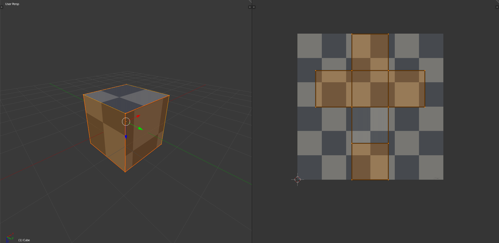
My current understanding of UV mapping is that any 3D mesh can be unwrapped so that its vertices, faces, and edges exist in a 2D space at which point a 2D texture can be mapped to these coordinates. If at a certain point in the 2D space, there is no defined face, but the texture is defined for that point, it is simply not applied to the model.

Example:

enter image description here

As you can see, only those parts of the texture defined within the bounds of the faces of the UV map on the right get mapped to the cube on the left.

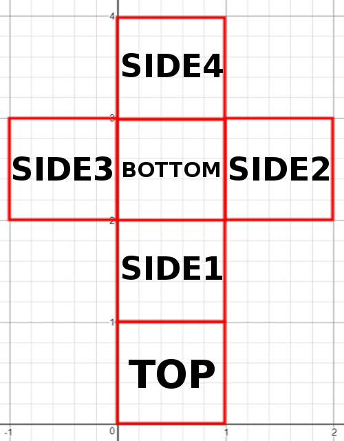
I, however, am trying to implement a UV map for 2D meshes onto 3D meshes instead of 2D textures onto 3D meshes. I realize that to generalize this problem is too difficult at least for me, so I began with a UV map of a cube as shown above. The code is simple enough for defining a UV map for a cube. Simply define the bounds of each face and supply a function which maps each uv coordinate, based on which face it is located on to a corresponding location in xyz coordinates of the 3D mesh.

Using that rationale I came up with the following (pseudocode):

//define an enum of faces which can be returned from functions
//added NOFACE in case a function can't return any of the faces
enum face = {TOP,
              BOTTOM,
              SIDE1,
              SIDE2,
              SIDE3,
              SIDE4,
              NOFACE};

class UVMapCube
{
    private:
        //define the bounds for every face in the order of [xMin, xMax, yMin, yMax]
        top = [0,1,0,1];
        side1 = [0,1,1,2];
        side2 = [1,2,2,3];
        side3 = [-1,0,2,3];
        side4 = [0,1,3,4];
        bottom = [0,1,2,3];
        scale = 1;

    public:

        //constructor
        UVMapCube(scale)
        {
            //scale up bounds based on the size of the mesh
            for(i = 0; i < 4; i++)
            {
                top[i] = top[i]*scale;
                bottom[i] = bottom[i]*scale;
                side1[i] = side1[i]*scale;
                side2[i] = side2[i]*scale;
                side3[i] = side3[i]*scale;
                side4[i] = side4[i]*scale;
            }

            this.scale = scale;
        }

        //return which face a given vertex lies in based on its UV coordinates using the bounds of each face
        //this is set up so that there is no overlap of faces
        face getFace(vertU,vertV)
        {
            if(vertU >= top[0] && vertU <= top[1] && vertV > top[2] && vertV < top[3])
            {
                return TOP;
            }
            else if(vertU >= side1[0] && vertU < side1[1] && vertV >= side1[2] && vertV < side1[3])
            {
                return SIDE1;
            }
            else if(vertU >= bottom[0] && vertU < bottom[1] && vertV >= bottom[2] && vertV < bottom[3])
            {
                return BOTTOM;
            }
            else if(vertU >= side2[0] && vertU < side2[1] && vertV >= side2[2] && vertV <= side2[3])
            {
                return SIDE2;
            }
            else if(vertU > side3[0] && vertU < side3[1] && vertV > side3[2] && vertV < side3[3])
            {
                return SIDE3;
            }
            else if(vertU >= side4[0] && vertU < side4[1] && vertV >= side4[2] && vertV <= side4[3])
            {
                return SIDE4;
            }
            else
            {
                return NOFACE;
            }
        }
        //return x,y,z coordinates on a cube based on UV coordinates on the map
        Vector3 map(vertU, vertV)
        {
            face f = getFace(vertU,vertV);
            if(f == BOTTOM)
            {
                return Vector3(vertU, 0, 3*scale-vertV);
            }
            else if(f == TOP)
            {
                return Vector3(vertU, 1*scale, vertV);
            }
            else if(f == SIDE1)
            {
                return Vector3(vertU, 2*scale-vertV, 1*scale);
            }
            else if(f == SIDE2)
            {
                return Vector3(1*scale, vertU-1*scale, 3*scale-vertV);
            }
            else if(f == SIDE3)
            {
                return Vector3(0, -vertU, 3*scale-vertV);
            }
            else if(f == SIDE4)
            {
                return Vector3(vertU, vertV-3*scale, 0);
            }
            else
            {
                return null;
            }
        }
}

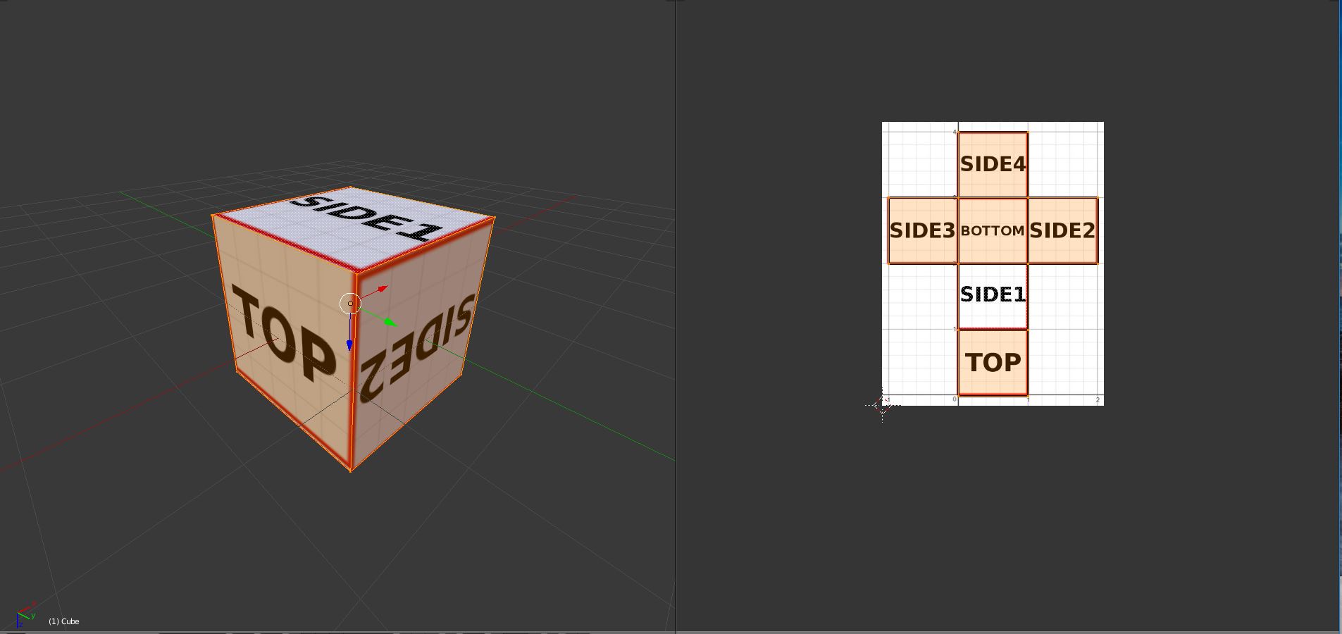
Graphically, it looks something like this:

enter image description here enter image description here

I got this far. However, the problems begin to arise when considering the "realtime" component of this "realtime UV mapping" approach.

Edit: I am aware that UV maps break the connectivity of the 3D Mesh they represent. However, for my purpose, if I am to implement a realtime UV map, I would need some way to ensure the connectivity of the 3D mesh is represented in the UV map in some artificial way. In other words, what do I do to ensure the user remains on the 3D mesh despite having moved "off" to an undefined location on the corresponding UV map.

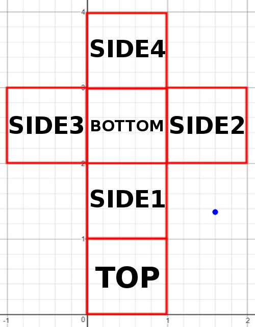
For example, where should I map the blue vertex in the example below:

enter image description here

The vertex location cannot be defined unless the vertex had some previous location on one of the defined faces of the map.

For one, if the vertex originates (its previous location before moving off the map) from Side1, it should be mapped somewhere on Side2. If it originates from Side2, it should be mapped somewhere on Side1. And if it originates from the corner of Bottom, Side1, and Side2, it should be mapped somewhere onto the edge shared by Side1 and Side2.

Am I missing something or will I have to simply figure out a bunch of special cases for mapping as I have been doing. Is there perhaps some mathematical approach which encompasses all of these cases completely or something known in the computer graphics community that I don't know?

Otherwise, if there is a better solution to my initial problem other than a "realtime UV mapping" approach, I would be glad to hear it.

Any help would be appreciated.

\$\endgroup\$
6
  • \$\begingroup\$ @DMGregory I modified my question to describe a more clear use case for this problem. \$\endgroup\$ Commented Jul 7, 2017 at 19:54
  • \$\begingroup\$ You are correct, however, imagine the player in a previous frame existed on the right edge of SIDE1. Now, one frame later, the player has moved to the right 0.5 units. Theoretically, the player should be teleported as soon as he passes this edge. However, for the moment, the amount the player intends to move surpasses that edge. I must now remap the player to the proper location and move him that 0.5 to the "right" (which is now up instead of right) on SIDE2. Since the game updates once each frame I can't necessarily catch exactly when he touches the edge. \$\endgroup\$ Commented Jul 7, 2017 at 22:02
  • \$\begingroup\$ Allowing the player to overshoot then re-mapping them based on their latest position is not a viable solution. Imagine their position is very close to the corner between two faces. Did they get there because they were in the face above and moved downward, or because they were in the face to the left and moved rightward? Each possibility gives a different destination to remap them to. So you can't get away from considering both the previous and latest position. Once you have that, you're better served raycasting the line between positions against the face edges, and teleporting when one is hit. \$\endgroup\$
    – DMGregory
    Commented Jul 7, 2017 at 23:11
  • \$\begingroup\$ Are you then saying that I should consider the raycasting solution using a previous and latest position or are you saying that if I am to use such an approach I might as well use the raycasting approach? If I shouldn't go that route, what alternatives do I have, because this is the only way I can see to approach this problem as of now. \$\endgroup\$ Commented Jul 7, 2017 at 23:18
  • \$\begingroup\$ Should the world appear to be flat to the player? If the answer is yes, then you have a more fundamental problem of how a world should look when someone is standing on a corner facing the seam between two other faces. \$\endgroup\$
    – Pharap
    Commented Aug 9, 2017 at 10:37

2 Answers 2

1
\$\begingroup\$

If you're doing "typical" operations, you can get away with a lot of intuitive shortcuts. They're intuitive because they're doing what the tool was intended to do. However, if you want to stretch beyond typical, it's best to understand what the math of UV mapping is really doing.

In all texture mapping, you're starting with a 3d mesh of triangles, and you're trying to assign a color to each point (whether that point is a vertex or simply a point inside the triangle). There are many ways to do this, of which UV mapping is only one method.

The fundamentals of UV mapping are very easy. You reduce the dimensional of the 3d mesh from 3 dimensions (x, y, z), to 2 dimensions which are given the labels u and v. You then use these 2 dimensions to decide what color to color each point (typically by doing a lookup from a 2d texture, as you have done). The key assumption is that, within any given triangle, a point's UV coordinates can be calculated by interpolating between the UV coordinates of each vertex (which turns out to be a really reasonable assumption in nearly all cases).

If you think formally like this, you can see that its possible there are points in this UV space that are not associated with a point on the mesh. Your blue dot is an example of that. It's a point in UV space that you simply cannot get by interpolating the UV values of the triangles on your particular mesh. That's all it is. So your question as to "where should I map the blue vertex" is a non sequitur. You don't have a blue vertex, you have a blue UV coordinate, which a vertex (or other point on a face) may be mapped to.

What that means to you is dependent on the precise problem you are trying to solve. To provide an example, if you are using the UV coordinates as a "hit map" of sorts, where you can click on the 2d bitmap and have it show you that point on the 3d mesh, then we can use the following rules:

  • Project the 3d mesh into 2d space (which is a fancy way of saying take every triangle on the 3d mesh, and starting thinking of it in terms of just UV coordinates instead of XYZ).
  • Whenever someone chooses a point on the bitmap, you can query this 2d mesh to see how many triangle contain that point.
    • If one triangle contains that point, you can use interpolation to identify the point in 3d space that associated with that UV coordinate
    • If multiple triangles contain this point, you can do the process on each triangle (its very common to abuse symmetry to have the left and right side vertices have the same UV coordinates).
    • If no triangles contain the point, then you are describing something that is "out of domain." You can decide what to do with this. For example, it may be very reasonable to pick the nearest triangle in the 2d space, and use it to extrapolate a 3d space point (outside of the triangle). If you did this, you'd find your point "vertex" outside of the object. This all depends on what is meaningful for your application. In some cases, where it's not obvious which triangle should "own" the out of domain point, you might even want to turn that 2d point into a 3d line or 3d curve to represent this information. It all depends on what your end user needs to visualize.
\$\endgroup\$
11
  • 1
    \$\begingroup\$ Thank you for the comprehensive response. However, I was being specific when I was describing a vertex. This is because in this particular case, I am mapping the vertices of a 2D mesh onto the surface of a 3D mesh. The 2D mesh will be controllable in realtime and from there arises my problem of points moving "off" the map. I would appreciate it if you could be more specific on your last point, where you describe turning the 2D point into a 3D line or curve. If you could better describe what that entails I would appreciate it. \$\endgroup\$ Commented Jul 7, 2017 at 20:03
  • 1
    \$\begingroup\$ What do you want it to mean when the mesh point is "off the map?" The domain of an inverse UV mapping (which is what you're doing) is defined by the existing 3d mesh projected into UV space. A point outside that projected mesh simply does not have an inverse mapping. This means you must define what that means to you, in your particular situation. Then we can start to explore what functions are best for extending the inverse UV mapping into what you want it to be. \$\endgroup\$
    – Cort Ammon
    Commented Jul 7, 2017 at 23:30
  • 1
    \$\begingroup\$ Well it's mostly a practical issue. I'm aware that this is beyond the traditional scope of a UV map. But in terms of what I'm trying to accomplish, I need to allow my user to move freely about the map, which in effect means he is controlling a 2D mesh that inhabits this map. That mesh will have vertices moving in realtime and what I want to find is an approach which allows me to keep my player on the surface of the 3D mesh even as he moves "off" the map. My question is essentially what is the best solution to keep a 2D mesh, wrapped onto the surface of the 3D mesh, in this case, as it moves. \$\endgroup\$ Commented Jul 7, 2017 at 23:36
  • 1
    \$\begingroup\$ Can you simply clip the user's 2d mesh so that its vertices cannot leave the valid domain of UV mapping? Alternatively, consider using only meshes which cover the entire domain which the user's 2d mesh may inhabit. \$\endgroup\$
    – Cort Ammon
    Commented Jul 8, 2017 at 3:01
  • 1
    \$\begingroup\$ My problem with doing the former is that, in the end I want the user to be able to navigate the entire surface of the 3D mesh and to be able to go in any direction on the 3D mesh at any point. So by clipping the 2D mesh to the valid domain of the map, I am effectively defining arbitrary boundaries on the mesh. My problem with the latter is there are very few meshes which, when unwrapped, cover the entire domain. That would require that the mesh be isomorphic with a flat 2d plane, which limits me to very few options. \$\endgroup\$ Commented Jul 8, 2017 at 13:16
0
\$\begingroup\$

Let me try to rephrase the question as I understood it:

  1. You have a 3D object surface unwrapped on to a UV map.
  2. You want to be able to pick a point on the UV map and get its location on the 3D mesh?

In that case, the solution would be to either:

  • make sure that whole UV map is "mapped". So there is not a single point on the UV map that is not belonging to some polygon.
  • or come up with an algorithm, that will find nearest polygon/vertex on UV map and take its location.

P.S. You also might want to ensure that no point on UV map belongs to more than 1 polygon - otherwise it would be troublesome to choose the right polygon to map it to.

\$\endgroup\$
2
  • \$\begingroup\$ Thanks for the reply. So, you did basically get the gist of the question, however I made an edit to clarify my specific use case for this problem. In your answer you said to make sure the whole UV map is "mapped" which would indeed solve my problem. However, that is exactly my problem. I cannot think of a general map which ensures that a vertex never lies on an undefined face. And to be more specific, my goal is to effectively map a 2D Mesh onto a 3D Mesh, but the 2D Mesh will be moving in realtime. \$\endgroup\$ Commented Jul 7, 2017 at 19:58
  • \$\begingroup\$ To do that, you'll have to deform and stretch the 2d projection. Think, why did you draw them as 2d squares? To fill the space, you can for example stretch side 4, top and side 1 in the horizontal direction until they fill the space. There are discontinuities, of course, but that's an unavoidable consequence of your chosen method. If you just want to navigate the surface of a cube, why not treat each face as standard 2d navigation, and when you get to the edge, switch face? \$\endgroup\$
    – Innovine
    Commented Aug 9, 2017 at 6:45

You must log in to answer this question.

Not the answer you're looking for? Browse other questions tagged .