5
\$\begingroup\$

So, the best way I can think of how to explain what I need is the following (images used here are just random images found trough google image search).

What I am trying to create during run-time is pretty much the same as a force shield that envelopes a robot or a space ship in many different futuristic types of games.

However, considering that these robots or ships have a shape that is unknown in advance, I don't want to just use a sphere-mesh around the ship or just assign a shield-shader directly to the ship mesh like in the pictures below:

enter image description here

I want to end up with a shield that is formed by a mesh that loosely represents the shape of the ship. Something like what can be seen in the pictures below:

enter image description here

However, I don't need those shields to be concave like in that pictures. It can be a convex mesh.

So far, what I've tried was to generate a sphere or a cylinder around the complex mesh (robot/ship), loop trough each vertex and try to approximate to the complex mesh. However, that is severely inefficient and gives non-smooth results.

Would you happen to have any idea, code sample, tutorial links, article references or anything on how can I proceed to get what I want in an efficient manner? The shields do not have to very detailed in terms of polygons. In fact, the less the better.

I am currently using C#, but I can handle C++ as well. Thanks in advance.

\$\endgroup\$
6
  • \$\begingroup\$ If you want something like on the bottom left image, you could compute approximate convex hull by stopping quickhull algorithm early and use the result mesh as control points for something like bézier or NURBS surface. But I would not want to implement that not even mentioning I am not sure if it worked for very single possible model. \$\endgroup\$
    – wondra
    Commented Nov 12, 2015 at 23:45
  • \$\begingroup\$ @wondra In fact, something similar to either bottom-left or bottom-right would be acceptable. My problems with approximate convex hull 3D algorithms are: 1) they actually generate mesh that is far too similar to the original mesh, thus loosing the shield aspect; 2) they usually generate meshes that are far from the rounded-pattern shields usually have. In the end convex hull is wasting process time: I have to calculate it just to then further simplify, smooth, etc on the generated mesh. Any suggestion? Maybe a technique that takes a simple mesh (cylinder, rounder box, etc) and re-shapes it? \$\endgroup\$
    – Andy Astro
    Commented Nov 13, 2015 at 1:19
  • \$\begingroup\$ You mention robots which have (?) articulating limbs - this is more difficult... there are a few options. A sphere is the safest bet. One alternative is to merge all possible frames of motion and create a single shield geometry from that - depending on how the waist may bend, it may not look very good. Another way that will look okay is to create a shield per frame, which might be costly to animate. Or, use the geometry shader on to bloat your mesh per frame on the GPU - Minkowski Sum may be possible and necessary here again. If you have a complex scene this may kill performance. \$\endgroup\$
    – Engineer
    Commented Nov 13, 2015 at 11:51
  • \$\begingroup\$ @ArcaneEngineer Sorry for the late reply, I had to travel. So, that's a very fair concern. However, for the case of animated beings with articulated limbs, I think one should have to use a much rougher approximation of the character shape. For instance, based on the compound of states it can be during animation or an ellipsoid-ish sphere around the OBB. Let's forget it for now and focus on the easier non-animated beings, that are already hard enough to accomplish in quality manners! \$\endgroup\$
    – Andy Astro
    Commented Nov 16, 2015 at 22:26
  • \$\begingroup\$ @wondra re-reading the comments here, I realized that I forgot to ask you a small piece of clarification. What exactly you mean by an approximate convex hull algorithm? Would it be something like waset.org/publications/16743/… ? Or by stopping quickhull early you just mean stopping the QuickHull 3D algorithm at the first k iterations trough the mesh vertices instead of doing all iterations needed for a perfect hull? \$\endgroup\$
    – Andy Astro
    Commented Nov 23, 2015 at 17:47

4 Answers 4

4
\$\begingroup\$

Each of your images describes a different algorithm. I would say the top two should not even be in the question. Bottom right is too angular to look good in-game, it looks like luggage in plastic cling-wrap. Let's focus on bottom left, the best looking approximation of the original mesh.

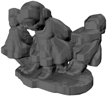
I think you want the 3D Minkowski sum of the original mesh, either (1) by getting a convex hull first and then applying the Minkowski summation algorithm to it, or (2) just do M-sum on its own. For a convex base mesh, the latter will have convex spaces, and inner corners may appear "pinched", see for example the space between the two children's heads at top left:

enter image description here enter image description here

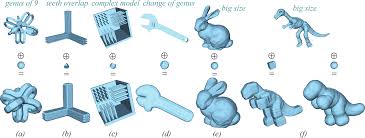
So you may do wish to do some smoothing after summation, depending on the sort of look you're going for. You'll also notice in the image above that a cubic mesh has been summed against the original mesh, which results in cubic artifacts, while in the image below, different operators are shown. You'll want pointwise or spherewise summation as shown for the dinosaur and bunny:

enter image description here

This technique is common in computational geometry and GIS applications, so you can find implementations in typical comp geom libs like GJK, CGAL etc. You could even download such and use it as proof of concept. I can't guarantee the performance on this will be great, since often those libs are not geared to real-time use. But it gives you a place to get started and you can a write a realtime implementation on your own (may require mesh reduction to get the required speed).

Note that voxelised Minkowski sum can yield better performance than traditional, more exhaustive approaches because the vertex count is strictly limited by the number of voxels. Google will help.

\$\endgroup\$
3
  • \$\begingroup\$ Many thanks for the thorough, detailed answer. So, first thing: conceptually, I quite liked your M-sum idea. It's fast and makes sense, but the result is a blobby bubble ship. Smoothing doesn't change much, although some mesh reduction helps. The convex hull 3D + M-sum is indeed promising, although I'm still to test whether the M-sum couldn't be replaced by re-scalig + smoothing algorithm alone. The problem, however, is of course performance: it looked great in 3D Studio for proof of concept, but it's still too slow when done within runtime game. I'm investigating how much I can tweak it \$\endgroup\$
    – Andy Astro
    Commented Nov 16, 2015 at 23:02
  • \$\begingroup\$ One question, though: would you have any idea on how to get that shield you rebuked as "luggage in plastic cling-wrap"? Since it's probably much more efficient in terms of processing, I tried the following as proof of concept. I hand-draw a very similar shape in 3D-studio and applied Y-symmetry modifier and then TurboSmoother modifier. It become great looking! So, if there is any idea on how to generate a simplistic ugly looking shield as that one, but in a way that's faster than convex hull 3D (which is a hungry algorithm), the ugly result might be quite improved with cheap post-processing \$\endgroup\$
    – Andy Astro
    Commented Nov 16, 2015 at 23:07
  • \$\begingroup\$ @AndyAstro Re "cling wrap": A decent convex hull generator should have options allowing you to restrict output to some vertex count. It may not be that simple however, as you'd be unable to review output quality before used unlike offline methods (Max). So you'd probably have to create a heuristic generator that takes as params for some ship, its surface area A, and outputs L vertices as the vertex limit - this is then passed into the convex hull generator - else maybe the shield looks bad. So as you see, the sliced approach is maybe a little easier. Also see comment on user3730788's answer. \$\endgroup\$
    – Engineer
    Commented Nov 24, 2015 at 18:24
4
\$\begingroup\$

Sliced 2D Convex Hulls Slice through the mesh (polygon + axis-aligned plane intersection), getting the convex hull of each resultant 2D polygon, e.g. from tip to tail for a ship like that in your image, or from head to toe in a humanoid - as you'd slice a carrot :) These could be equidistant slices or spaced according to some heuristic, but will describe the mesh with a good amount of accuracy albeit leaving out certain convex details. To clarify: You're not actually cutting up the original mesh, instead you're just taking scans through it's geometry, much like a CT scan - slices are frequently used in medical imaging applications. You can then scale each of these slices up, join / triangulate / tesselate them, and cap the mesh at each end with additional vertices.

EDIT In slicing down the length, you need to first get a cross section as though you are cutting the ship in left and right halves. Then calculate the 2D convex hull of that. The vertices of that 2D convex hull can be used to decide where you slice from nose to tail (like ribs). If not done, local maxima like spikes on the ships surface may be missed. The actual tip-to-tail slices may or may not be convex, but I guess skipping the convex hull calculation on these will result in lower cost overall.

This might suit what you're trying to do quite well, given your desire for efficiency - which is easy to tweak based on the number of slices - and your flexibility around concavity / convexity. EDIT Since you don't need convexity, this will likely be faster than general purpose quickhull, and a bit easier to conceptualise / configure / debug / control performance. But quickhull might just be more direct.

\$\endgroup\$
8
  • \$\begingroup\$ Now that one is pretty curious. I have to admit two things: first, I didn't quite understand what you mean. Second: still, it somewhat sounds promising. Would you care to elaborate on the idea? I got particularly confused by why that is a 2D convex hull problem. What I understood was that one could slice the ship mesh in a given direction, calculate the 3D convex hulls of each slice and then merge these multiple hulls. A process that would end up being faster than just calculating the overall 3d convex hull of the entire ship. Is that the idea? If yes, where the 2D comes from? Thanks! \$\endgroup\$
    – Andy Astro
    Commented Nov 16, 2015 at 23:10
  • \$\begingroup\$ @AndyAstro Almost got it. When you slice, you're taking 2D cross-sections. To use the carrot-slicing analogy: Imagine slicing a carrot through the middle, dipping one of the sliced ends in ink, and using it as a stamp. The resulting mark is a 2D cross section of the carrot at that point. Now slice and stamp several more times. As the shape of the carrot varies through it's length, you're going to get different stamps as you keep doing that. Now we take these cross sections, and reassemble them using longitudinal edges, like ribs/arches that you're now joining lengthwise with bits of wire. \$\endgroup\$
    – Engineer
    Commented Nov 17, 2015 at 10:52
  • \$\begingroup\$ Obviously, the triangulation between each distinct pair of cross sections is up to you, since each cross section will have different vertex counts and vertices in different positions. But it should be quite trivial to tesselate it sanely. Also, Google "Stephen Biesty cross sections" and you will see some cool examples of longitudinal cross sections through different vessels / vehicles (heli, shuttle, galleon). \$\endgroup\$
    – Engineer
    Commented Nov 17, 2015 at 10:55
  • \$\begingroup\$ Ah, I have found memories of Stephen Biesty's books, thanks for reminding me of him! So, I think I see where you are going with 2D slice: I could get the 2D convex hull of each slice and then connect all together to get a overall hull. The only thing is: for that to not leave parts of the ship piercing its on shield, there would have to be a huge number of slices (at very tiny distance intervals). I though of swiping a plane across the ship and detecting the intersections as a way to not miss any irregular parts \$\endgroup\$
    – Andy Astro
    Commented Nov 20, 2015 at 21:52
  • \$\begingroup\$ Then every iteration when the plane moves, I would have to check all edges (that have one vertex at each side of the place) against that plane to detect point of intersection. Of course I have no idea if that will prove to be faster or slower than a plain 3D convex quickhull algorithm. It seems slower, but ultimately, if I don't find a quick enough way, it would be at least interesting to make such comparison \$\endgroup\$
    – Andy Astro
    Commented Nov 20, 2015 at 21:54
2
\$\begingroup\$

For a nice artistic look you can voxelize your model in a grid them perform marching cubes. That is you'd end up with a shield with as little or as much detail as you want depending on the grid size. You can also perform a post-processing step on the voxelized grid data to smooth out the mesh before generating the triangles. Or perform a step afterwards to remove unneeded vertices or smooth the mesh (there's probably other algorithms) to get a different look.

\$\endgroup\$
1
  • \$\begingroup\$ Thanks for the idea. I think for many artistic styles, marching cubes might indeed be a nice solution, depending on their computational cost. However, I'm looking for a solution that gives a more simplified-looking mesh. I'm here researching on the possibilities of smoothing the mashes generated with marching cubes to see how would that look like. \$\endgroup\$
    – Andy Astro
    Commented Nov 13, 2015 at 1:23
1
\$\begingroup\$

One method is to create a mesh by iterating over every vertex of your object and make a vertex normal to the objects surface at that point with an arbitrary magnitude (magnitude of 0 means the shield is the surface). As mentioned this takes time O(cN) where N is the number of points in your original objects mesh.

Now if you want to handle any possible shape or configuration you can attempt to create an easy shape, for example spheres, for each different "part" of the object, then combine the meshes so they do not do not overlap inside the object. If you can efficiently (tree hierarchy) determine the different part of the ship and remove any points in the other mesh this might get where you are trying to go.

\$\endgroup\$
4
  • \$\begingroup\$ Thanks for replying. However, I didn't understand exactly what you are proposing. It would be to generate a shield-mesh from scratch by iterating over each vertex of the ship/robot mesh by following their normals? \$\endgroup\$
    – Andy Astro
    Commented Nov 13, 2015 at 1:21
  • \$\begingroup\$ That is one option. It's cost scales directly with the number of external vertices in your objects mesh. Another option that strikes me is you can calculate collision with your object at scale and centered on your object but don't render it. Then you have a space ship around your space ship \$\endgroup\$ Commented Nov 13, 2015 at 4:40
  • \$\begingroup\$ @user3730788 Nope, that only works with fundamentally convex ships, because with concave ones you will end up with the shield intersecting concave areas if you just scale it. This is why I talk about the Minkowski sum in my answer - it scales equally in all areas, it "chubbifies" the model. \$\endgroup\$
    – Engineer
    Commented Nov 24, 2015 at 16:34
  • \$\begingroup\$ Intersecting itself is not an insolvable problem but it does require additional calculation to remove internal vertices and mend the mesh. "..., nothing in this world is free." \$\endgroup\$ Commented Nov 26, 2015 at 0:15

You must log in to answer this question.

Not the answer you're looking for? Browse other questions tagged .