But does tilting the camera cause the same changes in the perspective of the lines as moving the camera lower to the ground (closer to the lines)?
No, it is not the same. To angle the camera to look below the horizon is not equivalent to move the camera closer to the ground while remaining level with the ground. In fact, tilting the camera will offset things vertically by some amount, including the vanishing point. On the other hand, changing the position of the camera will change the slope of the lines.
With that said, thinking in terms of vanishing point is not the best approach. Vanishing point are an emerging property of the geometry of objects and perspective.
And I mean by that, that a different geometry (I mean different shapes and orientations, not different metrics, nor different topologies) may result in different apparent vanishing points※, which may even be exploited for optical illusions.
※: I am claiming that the main difference between one-point, two-point and three-point perspective is the shape and orientation of the object, and not anything about the math behind it.
I need to define the principal of the camera. I prefer to refer to it as the principal line of sight. You can find it with other names such as "princial axis", "principal ray", etc.
It is the line that goes from the position of the camera, to the point that is projected at the center of the image. It is forward vector of the camera if you are working on a game engine.
If you have your camera level with the ground (a.k.a the ground is parallel to the principal of the camera), the horizon will stay at the center of the image.
You are probably familiar with this effect. It is often worded as saying that the horizon on the picture is at the height of the eyes of the viewer:

The vanishing point and horizon line are at the height of the eyes of the viewer.
We are used to have a camera that is level with the ground. However, that is not always the case.
Now, we say we have a one-point perspective when the scene has mainly lines that are parallel or perpendicular to the principal of the camera. In this case you will have a single vanishing point at the center of the image.
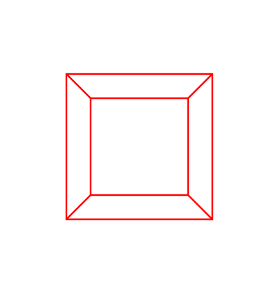
A cube depicted in one point perspective.
Notice in the image that the depicted cube only have lines parallel or perpendicular to the principal of the camera. As a result it has a single vanishing point at the center of the image.
Then, when you tilt the camera. The scene no longer have mainly lines that are parallel or perpendicular to the principal of the camera... because changing the orientation of the camera changes the principal of the camera. As a result you end up with a two point perspective. That is, it will have two main vanishing points.
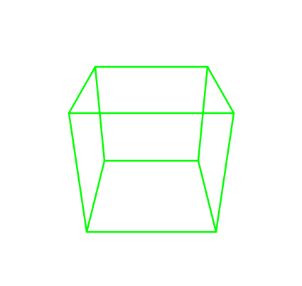
A cube depicted in two point perspective.
In this second image, the cube has been rotated. It no longer have lines that are parallel or perpendicular to the principal. In fact, if you group lines by how much they change in depth you end up with three sets, of which one does not change at all (these lines remain perpendicular to the principal of the camera). Thus, it has two vanishing points.
Notice also that the lines that do not change in depth will remain parallel instead of going to a vanishing point. We can say that lines that lie on planes perpendicular to the principal of the camera (that is, the normal of the plane matches the principal of the camera) are in true size, will not appear distorted by perspective (just scaled) and will not have a vanishing point.
If we now rotate the camera to an angle where there are no longer lines perpendicular to the principal of the camera we end up in three point perspective.
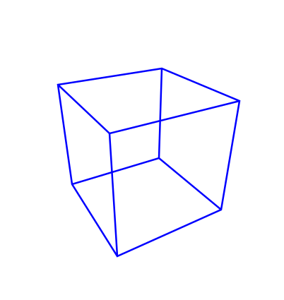
A cube depicted in three point perspective.
Notes:
- All of these emerge from the same math we use to make a perspective projection.
- It is possible to create a projection starting by defining the vanishing points for the main axis of an scene (it could be by placing them at infinity), doing so will allow for projections that do not match how cameras work.
- An image may appear to have more than three vanishing points. This is due to the shape and orientation of the object it contains.
- Isomorphic, if you are curious, would place the vanishing points for the main axis of the scene in an equilateral triangle. You can get it by using the angles 45º and 35.264º (aprox)
- There are also skwed projections (such as the oblique projections), they are off topic here.
Our objective is to capture the behaviour of a pinhole camera. We are disregarding depth of field, optical and chromatic aberrations. That is, we only care about the geometry.
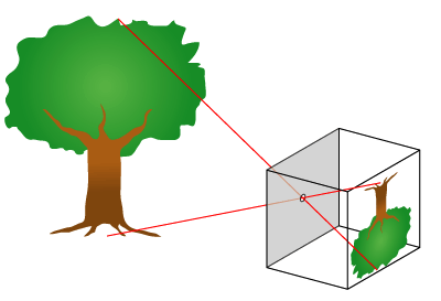
Our pinhole camera has:
- Focal length
- Position
- Orientation
Notes:
- The Focal length of the pinhole camera is the depth of the camera (from Latin camera "a vault, vaulted room").
- The pinhole camera also have an apperture size. The apperture affects depth of field (what is the distribution of things in focus) and exposure, it and may introduce some aberrations such as Vignetting. We do not care of any of that.
The first step is to transofrm the world space into camera space. That is, we need to do a coordinate system transformation such that the camera ends up at the origin, looking down the z axis and with the x and y axis corresponding to the camera Roll.
Once you have your system in camera space, doing an orthogonal projection is trivial: take the x and y coordinates, scale and offset to match the viewport.
However, instead we want perspective. Thus, what we are going to do is scale things depending on the distance to the camara (their position on the z axis).
Consider a transformation of the form:
(x, y, z) = (x, y, z) * func(z)
Where * denotes scalar product.
Note: remember that we do not plan to use the z coordinate.
Notice that the pinhole model yields a flipped image. While we can just invert the coordinates after we are done. It is simpler to think of it as placing the projection plane in front of the camera instead of behind. The model now looks like this:
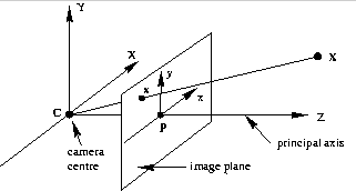
Ah, geometry, we can solve this. We can separate the axis, and the result will be a similar triangle problem.
Since we have similar triangle, it follows that:
x'/f = x/z
Where x' is the image x coordinate, x is the camera space x coordinate, f is he focal length, and z is the camera space z coordinate.
It follows that:
x' = x*f/z
Thus:
(x, y, z) = (x, y, z) * f/z
Alright, but you do not want to work with points, you want to work with lines...
Let us say we have - in camera space - a line running along the floor (y = 0) in one-point perspective (x = k). In this case x' = k*f/z and y' = 0.
Alright, now let us define a line tilted vertically with a knonw slope m and starting at c below the camera. For this line we have y = z*m-c and x = k. We need to define it in parametric form:
x = k
y = t*m-c
z = t
And transform:
x' = k*f/z
y' = (t*m-c)*f/z
z' = t*f/z
Replace z:
x' = k*f/t
y' = (t*m-c)*f/t
z' = t*f/t
Simplify:
x' = k*f/t
y' = m*f - c*f/t
z' = f
Let us try to get a nominal line equation:
x' = k*f/t

=>

x'/k = f/t

---

y' = m*f - c*f/t

=>

y' = m*f - c*(x'/k)

=>

y' = m*f - x'*c/k

=>

y' = - x'*c/k + m*f
Demo 1
The following code implement the line equation we figured out. It will render 5 parallel lines, with an offset of 0.1 on the x axis among them. This will ease to visualize how it works.
I am using a library designed for plotting math functions. It takes as input the function as a string. I did this so that it is clear on the code when I am using the function, and that - in fact - I am using the function I claim to be using. In general, this library reduces the amount of code I need to draw the lines based on the line equations without making then unrecognizable. As a side effect, the code is slow.
Important: This code is slow.
let draw = function() {
  // y' = - x'*c/k + m*f
  let c = $('#c').val();
  let k = $('#k').val();
  let m = $('#m').val();
  let f = $('#f').val();
  if (c === '' || k === '' || m === '' || f === '') {
    return;
  }
  k = parseFloat(k);
  let fna = 'x*(' + c + ')/(' + k + ') + (' + m + ')*(' + f + ')';
  let fnb = 'x*(' + c + ')/(' + (0.1 + k) + ') + (' + m + ')*(' + f + ')';
  let fnc = 'x*(' + c + ')/(' + (0.2 + k) + ') + (' + m + ')*(' + f + ')';
  let fnd = 'x*(' + c + ')/(' + (-0.1 + k) + ') + (' + m + ')*(' + f + ')';
  let fne = 'x*(' + c + ')/(' + (-0.2 + k) + ') + (' + m + ')*(' + f + ')';
  $('#fn').html('y = ' + fna);
  functionPlot({
    target: '#plot',
    data: [{
        fn: fna
      },
      {
        fn: fnb
      },
      {
        fn: fnc
      },
      {
        fn: fnd
      },
      {
        fn: fne
      }
    ]
  })
};
let initialize = function() {
  $('#draw').click(draw);
  $('input[type=number]').change(draw).keyup(draw);
};
$(document).ready(initialize);
input {
  width: 18%;
}
<script src="https://ajax.googleapis.com/ajax/libs/jquery/2.1.1/jquery.min.js"></script>
<script src="https://d3js.org/d3.v3.min.js"></script>
<script src="https://wzrd.in/standalone/[email protected]"></script>
<input type="number" id="k" placeholder="x" step="0.1">
<input type="number" id="c" placeholder="camera elevation" step="0.1">
<input type="number" id="m" placeholder="slope" step="0.1">
<input type="number" id="f" placeholder="focal length" step="0.1">
<input type="button" id="draw" value="draw"> Formula: <span id="fn"></span>
<div id="plot"></div>
I suggest start by setting a slope of 0, a focal length of 1, some positive camera elevetion and then move x and camera elevation. You may then move to play with slope and focal length to see how they affect the picture.
Note:
- Camera elevation here is the vertical distance from the lines to the camera, not an angle. To manipulate the inclination use slope.
- If you only move x and elevation, you are not changing the orientation, and thus the vanishing point stays fixed.
- If you put elevation at 0, the camera is on the same plane as the lines. At this point, all lines are horizontal.
- This library will not plot equations that result in division by 0 when evaluating. Games will often define lines with position and director vectors instead of using line equations to avoid dealing with this problem.
Important: This code is slow.
For the sake of it, let us work out how to add horizontal lines.
I will define this lines with z = a, y = -c and x = t:
x = t
y = -c
z = a

=>

x' = t*f/z
y' = -c*f/z
z' = a*f/z

=>

x' = t*f/a
y' = -c*f/a
z' = a*f/a

=>

x' = t*f/a
y' = -c*f/a
z' = f
Note: as we can see y is constant.
Let us do it more interesting. Let us define these horizontal lines to be on the same plane as the lines we defined before:
x = t
y = a*m-c
z = a

=>

x' = t*f/z
y' = (a*m-c)*f/z
z' = a*f/z

=>

x' = t*f/a
y' = (a*m-c)*f/a
z' = a*f/a

=>

x' = t*f/a
y' = (a*m-c)*f/a
z' = f

=>

y' = (a*m-c)*f/a - (a*m-c)*f/a

=>

y' = a*m*f/a - c*f/a

=>

y' = m*f - c*f/a
Demo 2
Same as above, but I have added horizontal lines (they are all pink).
let draw = function() {
  // y' = - x'*c/k + m*f
  let c = $('#c').val();
  let k = $('#k').val();
  let m = $('#m').val();
  let f = $('#f').val();
  if (c === '' || k === '' || m === '' || f === '') {
    return;
  }
  k = parseFloat(k);
  let fna = 'x*(' + c + ')/(' + k + ') + (' + m + ')*(' + f + ')';
  let fnb = 'x*(' + c + ')/(' + (0.1 + k) + ') + (' + m + ')*(' + f + ')';
  let fnc = 'x*(' + c + ')/(' + (0.2 + k) + ') + (' + m + ')*(' + f + ')';
  let fnd = 'x*(' + c + ')/(' + (-0.1 + k) + ') + (' + m + ')*(' + f + ')';
  let fne = 'x*(' + c + ')/(' + (-0.2 + k) + ') + (' + m + ')*(' + f + ')';

  // ---

  let fnxa = '(' + m + ')*(' + f + ')-(' + c + ')*(' + f + ')/(' + 1 + ')';
  let fnxb = '(' + m + ')*(' + f + ')-(' + c + ')*(' + f + ')/(' + 2 + ')';
  let fnxc = '(' + m + ')*(' + f + ')-(' + c + ')*(' + f + ')/(' + 3 + ')';
  let fnxd = '(' + m + ')*(' + f + ')-(' + c + ')*(' + f + ')/(' + 4 + ')';
  let fnxe = '(' + m + ')*(' + f + ')-(' + c + ')*(' + f + ')/(' + 5 + ')';
  let fnxf = '(' + m + ')*(' + f + ')-(' + c + ')*(' + f + ')/(' + 6 + ')';

  $('#fn').html('y = ' + fna);
  functionPlot({
    target: '#plot',
    data: [{
        fn: fna
      },
      {
        fn: fnb
      },
      {
        fn: fnc
      },
      {
        fn: fnd
      },
      {
        fn: fne
      },
      {
        fn: fnxa, color: 'pink'
      },
      {
        fn: fnxb, color: 'pink'
      },
      {
        fn: fnxc, color: 'pink'
      },
      {
        fn: fnxd, color: 'pink'
      },
      {
        fn: fnxe, color: 'pink'
      },
      {
        fn: fnxf, color: 'pink'
      }
    ]
  })
};
let initialize = function() {
  $('#draw').click(draw);
  $('input[type=number]').change(draw).keyup(draw);
};
$(document).ready(initialize);
input {
  width: 18%;
}
<script src="https://ajax.googleapis.com/ajax/libs/jquery/2.1.1/jquery.min.js"></script>
<script src="https://d3js.org/d3.v3.min.js"></script>
<script src="https://wzrd.in/standalone/[email protected]"></script>
<input type="number" id="k" placeholder="x" step="0.1">
<input type="number" id="c" placeholder="camera elevation" step="0.1">
<input type="number" id="m" placeholder="slope" step="0.1">
<input type="number" id="f" placeholder="focal length" step="0.1">
<input type="button" id="draw" value="draw"> Formula: <span id="fn"></span>
<div id="plot"></div>
Important: This code is slow.
Final note:
If anybody out there is thinking, "hmm, I could make a 3D engine using this", let me tell you... I have been there, when I was young and naive. First off all, 3D engines use matrix transformations for all this stuff and for good reason. So if you want to do something like that (say, for example, to make a 3D game using excel, or some other cute use case like that) improve your knowledge of linear algebra first. Second, if you want to know how 3D graphics works, go learn about pixels and triangles. And third, if you want to develop 3D video games, you do not need to figure out this stuff yourself… all modern 3D solutions have matrix transformation math embedded in already for you to use. If you do not want to use a game engine (such as Unity) go learn OpenGL or something.


