4
\$\begingroup\$

enter image description here The game Teleglitch heavily utilizes the CA effect with screen distortion.

I am trying to achieve this effect.

Issue 1. How to not apply the effect onto the floor? (solved) enter image description here

They render the screen then apply the CA effect. However, the floor is not rendered with the post processing effect. enter image description here

Issue 2. How to have discoordinated position for each rendered CA effect?

Currently I have three offsets for each channel: red, green, and blue. However, I cannot assign different offsets for the channels for certain areas only. What would be a way to have discoordinated positions?

\$\endgroup\$
2
  • \$\begingroup\$ Could you expand on your question under "Issue 2"? It is not clear to me what you are asking/trying to achieve. Even some form of diagram illustrating what you would like to produce might help for understanding. \$\endgroup\$ Commented Jun 8, 2015 at 10:53
  • \$\begingroup\$ It's best for the StackExchange format to ask one question at a time, so I'd recommend splitting your two issues into two distinct questions. You'll likely get better answers to each that way than by trying to bundle them together. \$\endgroup\$
    – DMGregory
    Commented Jun 9, 2015 at 12:54

2 Answers 2

5
\$\begingroup\$

enter image description here

enter image description here enter image description here

Welcome to the tutorial to discooridnated chromatic effect. The above is an example of screen distortion. It is necessary to understand the first type of screen distortion in order to understand the final effect listed second.

It is achieved by having screen coordinate texture then applying the altered screen coordinate when rendering the final scene.

Better to see what's happening then read description. Let's take a look at the debug screen.

enter image description here

I use this green texture of color .5 .5 0 as my new coordinate texture. Why .5 .5 0? Because red value is used for x coordinate and green value is used for y coordinate. And because default value for coordinate change of the screen should be 0, 0. And .5 .5 0 gives you coordinate change value of 0, 0.

The equation for translating the color pixels to coordinate is following.

final_coordinate = original_coordinate + (colorPixel - (.5 , .5) ) / .5;

This effect only takes three lines of code. That's right. Three lines then you are good to go.

fixed4 GetColor(sampler2D main, sampler2D src, float2 uv){
            //main is the main screen texture. src is the green texture, uv is the original screen coordinate for the pixel
            float4 color = tex2D(src,float2(uv.x,1-uv.y));
            float2 coordinate = (color.rg - float2(.5,.5) ) /.5;
            return tex2D(main,uv + float2(coordinate.x,coordinate.y) );
        }

fixed4 frag(vertex  i) : COLOR  {
            return  GetColor (_MainTex,_DistortionCoordinateTextue, i.uv );
        }

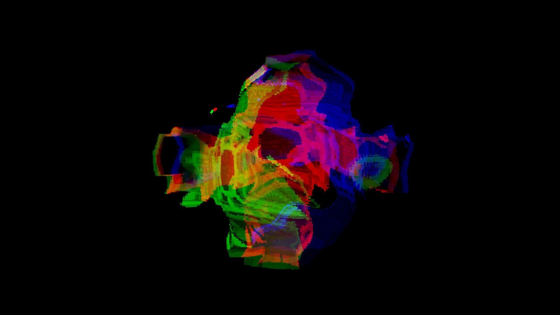
However the effect we want to achieve is not a simple screen distortion but color channel based screen distortion.
enter image description here

All we need to do is repeat the step above three times for each color of the pixel; red, green, and blue.

In order to distort three times, we are going to need three distortion fields.

fixed4 frag(vertex  i) : COLOR  {
            float4 originalColor = tex2D(_MainTex,i.uv);
            float4 r = GetColor (_MainTex,_distortionRed, i.uv );
            float4 g = GetColor (_MainTex,_distortionGreen, i.uv );
            float4 b = GetColor (_MainTex,_distortionBlue, i.uv );

            return float4(r.r,g.g,b.b,originalColor.a);
        }

\$\endgroup\$
0
\$\begingroup\$

I'm not sure if this method is completely possible with unity/shaders, but I think this is a method that could work.

For each colour channel; define what I would call a "warp field". A "warp field" in this case would be a 2 dimensional array of Vector2s, with each element corresponding to a pixel on screen. (you could have this representation at a lower resolution, and upscale/interpolate to reduce performance impact.

The elements in this array represent a distortion for that colour channel, effectively stretching/warping parts of the image. For example:

Warping example

Interpolation would be used to fill in the areas where the pixels have been stretched apart or pushed together.

(This next section is off the top of my head, and may not work/ be as easy to implement)

The next problem is generating warp information for a good looking distortion effect. This could be achieved by simulating a 2d grid of spring-connected points and populating the warp field with the vector from a nodes rest position to its current position.

This grid of points can then have forces applied to it to give the distortion wobbly kind of effect (you would use different magnitudes of force/altered directions for the different colour channels).

A 3d version of the spring-grid simulation I am imagining: https://www.youtube.com/watch?v=ib1vmRDs8Vw

\$\endgroup\$
3
  • 1
    \$\begingroup\$ In rendering this technique is often called "indirect texturing" - the warp field is usually encoded as a texture, and its rgba values are interpreted as components of the offset vectors. The shader first samples the warp texture one or more times to get its offsets, then uses those offsets to bias the lookup into the displayed texture. Simulating a set of springs in a texture is expensive, but you may find you get good enough effects simply by scrolling the warp texture across the screen in a different direction for each of the r,g, and b colour planes, so that their offsets are uncorrelated \$\endgroup\$
    – DMGregory
    Commented Jun 9, 2015 at 12:51
  • \$\begingroup\$ That makes sense, I haven't directly worked with shaders before but it makes sense to encode the warp field in texture memory to get the performance benefit of running the code as a shader. You are right about the simulation being expensive, I'm sure there must be a much cheaper way to fake that data \$\endgroup\$ Commented Jun 9, 2015 at 13:21
  • \$\begingroup\$ A simple Perlin noise heightmap should suffice as the warp texture. \$\endgroup\$
    – d3dave
    Commented Jun 13, 2015 at 19:53

You must log in to answer this question.

Not the answer you're looking for? Browse other questions tagged .