1
\$\begingroup\$

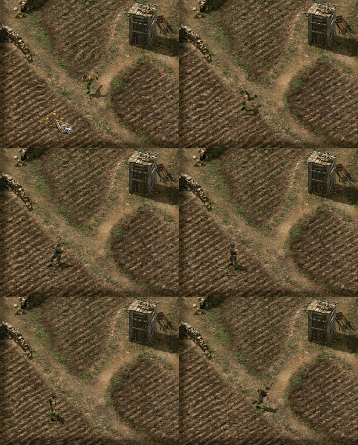
I would like to implement the following running effect in Unity. When the player character moves, it creates some sort of rings around it to give the impression of high speed.

enter image description here

I have searched for shockwave effects, ripple effects, water-drop effects but I either (1) could not get them to work on a specific region of the screen (most were post-processing effects that work on the whole screen), or (2) they did not look like this one.

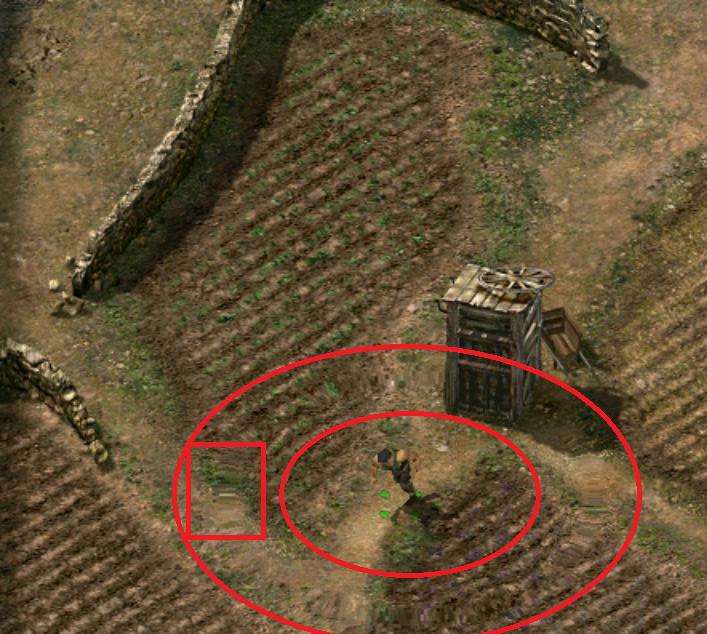
I then tried to reverse-engineer this effect -- visually that is. I grabbed a screenshot of the player movement and it shows the following.

enter image description here

So basically I noticed a ring around the player where the terrain image is distorted. I have constrained that ring within the red ring to show it better. I have also added the red box to bring your attention to the image distortion I am talking about.

So my naïve interpretation of this effect is that it creates few rings of increasing size around the player, and it shows them one by one over time.

This kind of reduces my problem to creating one ring that blurs the terrain image like shown in the screenshot: some sort of elongated blurred pixels.

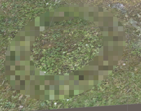
Now, I know next to nothing about shaders. I found this page (How to apply Image effect only on specific part of objects?) that implements a pixelating shader that can be applied to an object. So I used it as a starting point. I now have this ring:

enter image description here

and I need help changing the following shader function (taken from the previous link) to show the kind of distortion I want.

float4 frag(v2f IN) : COLOR
{
    float2 steppedUV = IN.grabPos.xy / IN.grabPos.w;
    steppedUV /= _PixelSize / _ScreenParams.xy;
    steppedUV = round(steppedUV);
    steppedUV *= _PixelSize / _ScreenParams.xy;
    //Sampling GrabTexture according to screen capture positon, tex2DProj is equivalent to tex2D (grabPos.xy / grabpos.w)
    return tex2D(_GrabTexture, steppedUV);
}

Any help is very much appreciated.

\$\endgroup\$
0

1 Answer 1

1
\$\begingroup\$

You normally do these things as a screen-space effect, by sampling the camera's opaque texture (if you use shadergraph, that would be the scene color node).

If you'll forgive me the lack of actual code, the general idea is to create a transparent mesh for the effect which is colored by sampling the opaque texture, using the screen-space coordinates of the fragment plus some offset. The offset is what creates the distortion.

In order to find the offset you could use the UV coordinates of the fragment. In this case, where the distortion is radial, the offset could be something like

offset = normalize( uv-float2(0.5,0.5) )

assuming, of course, that the center point of the mesh has UV=(0.5, 0.5)

To fully recreate the effect you show you also need to animate this, but I think this should be enough to get you started.

Edit:

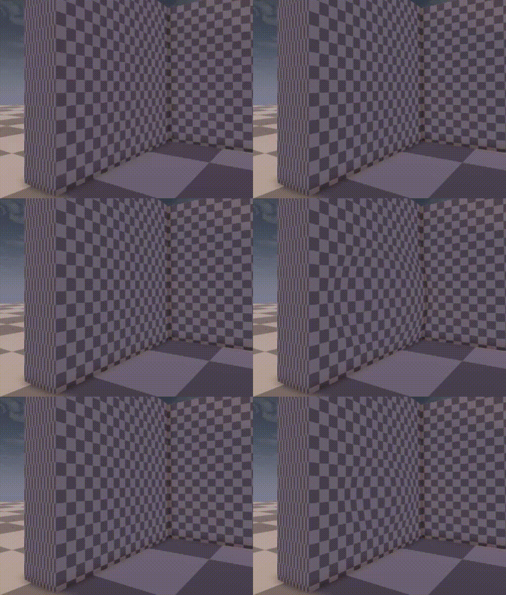
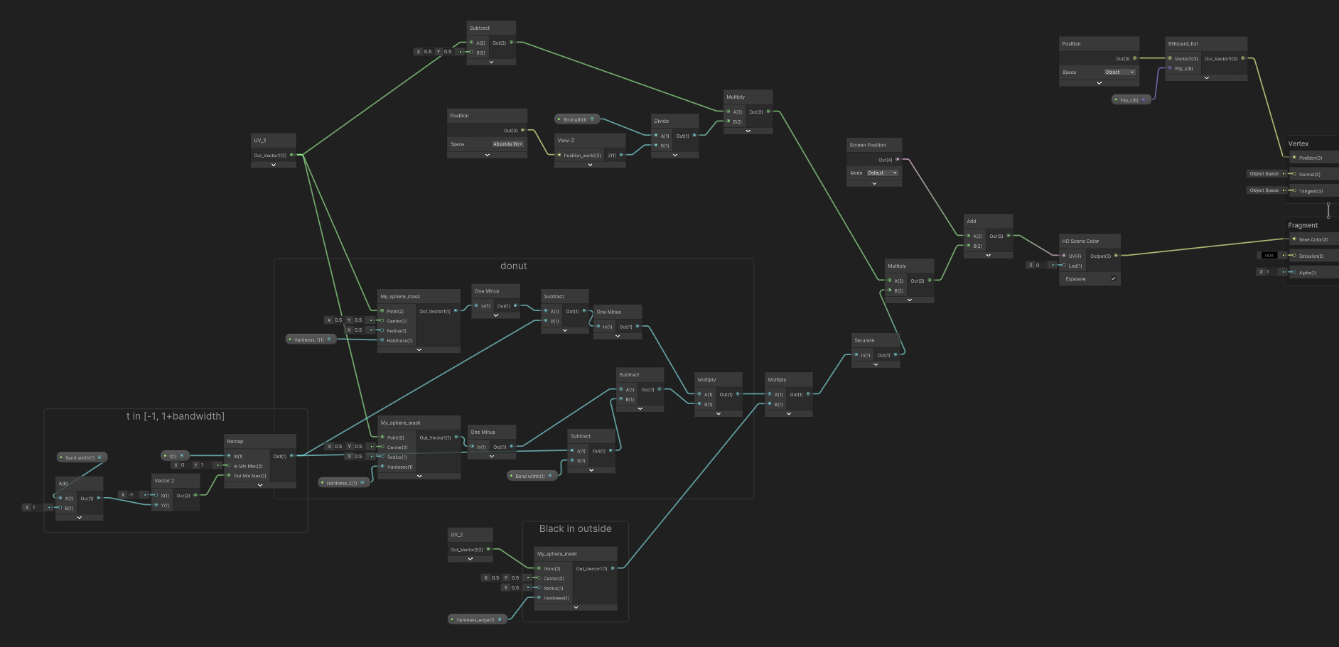
Okay, so here's my shadergraph version of a very similar thing. The distortion effect. It's pretty cool.

Shadergraph version of the thing. It's lots of nodes connected to each other, so describing is tricky

The most important part is this: Offset the coordinates at which to sample the scene color by the UV coordinates of the fragment minus (0.5, 0.5)

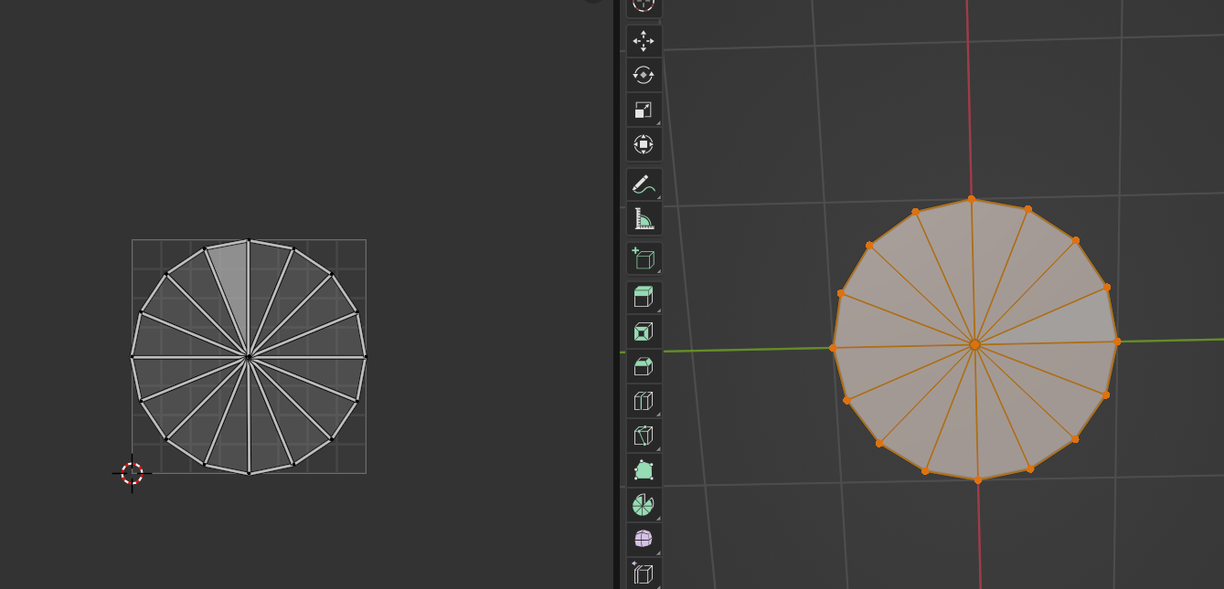
That is where the opaque texture (the scene color) is sampled. Basically, you want to figure out which pixel this fragment would be rendered to, and sample the color of a different pixel, with a relative offset. The offset, in this case, is calculated from the UVs. For that to work, you need a mesh that really has UVs (0.5, 0.5) at the center. Kind of like this:A circle mesh, unwrapped so that the center is at (0.5, 0.5)

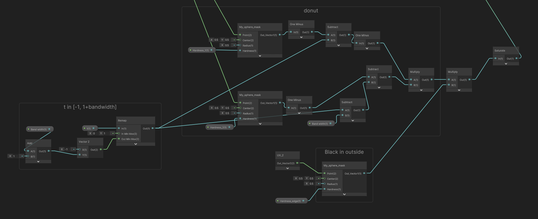
Other than that, what the shader is doing is calculating a donut-like mask by combining multiple sphere masks (well, circles, really, but whatever), so that the entire thing is not getting distorted at the same time. By changing the parameter t, you can make it flow from the center outward.more nodes, I'm sorry

Don't be scared by the fact that this uses a custom sphere mask node. The built-in one would work just fine, it's just that I'm insufferable and I needed to make it so that the effect starts exactly at t=0 and ends exactly at t=1.

The other thing you might see is a billboarding node in the vertex shader, but that really is beyond the scope of this question, I think.

\$\endgroup\$
5
  • \$\begingroup\$ Thanks @PepeOjeda. I unfortunately could not make much sense of your description as I lack a lot in shader jargon. Are you by any chance referring to something like this forum.unity.com/threads/simple-optimized-blur-shader.185327? \$\endgroup\$
    – Minoush82
    Commented Jun 20, 2022 at 7:55
  • \$\begingroup\$ Yes, quite similar to that. In this case, that "_GrabTex" field is what I'm referring to as the "opaque texture" (I believe the terminology is different for each rendering pipeline, which adds a lovely amount of extra confusion). In any case, it is a texture that contains the result of rendering all opaque objects. If you sample it in a transparent shader, you can access the color that was rendered to that pixel. By itself, not very useful. However, if you sample the color of a different pixel (hence, the offset) and apply it to the current one, you get distortion! \$\endgroup\$
    – PepeOjeda
    Commented Jun 20, 2022 at 8:18
  • \$\begingroup\$ I never got that one to work correctly. I basically created an object (e.g. cube) to which I apply the blur shader, and by looking through the cube in the scene, I can see the world blurred behind it. This worked perfectly in a dummy project I created to test the shader. But when I tried to incorporate into my main project, I needed to zoom in with the camera so close to the cube to be able to see the world blurred behind. I could not figure out for the life of me why I am getting this different behaviour. Both cameras (in my main project and in the dummy project) have the same parameters. \$\endgroup\$
    – Minoush82
    Commented Jun 20, 2022 at 8:25
  • 1
    \$\begingroup\$ Well, distance is definitely relevant for this sort of screen-space effect. When I get home later today I can share a shadergraph version of almost exactly the ripple effect you want, including this distance-correction business. However, I am not well-versed in writing code shaders for the built-in RP, so I'm afraid I must leave you to figure out the implementation details on your own. \$\endgroup\$
    – PepeOjeda
    Commented Jun 20, 2022 at 8:35
  • \$\begingroup\$ Many thanks for your help! \$\endgroup\$
    – Minoush82
    Commented Jun 20, 2022 at 8:37

You must log in to answer this question.

Not the answer you're looking for? Browse other questions tagged .