15
\$\begingroup\$

I see a few broad approaches out there to doing cel shading:

  1. Duplication & enlargement of model with flipped normals (not an option for me)
  2. Sobel filter / fragment shader approaches to edge detection
  3. Stencil buffer approaches to edge detection
  4. Geometry (or vertex) shader approaches that calculate face and edge normals

Am I correct in assuming the geometry-centric approach gives the greatest amount of control over lighting and line thickness, as well eg. for terrain where you might see the silhouette line of a hill merging gradually into a plain?

What if I didn't need pixel lighting on my terrain surfaces? (And I probably won't as I plan to use cell-based vertex- or texturemap-based lighting/shadowing.) Would I then be better off sticking with the geometry-type approach, or go for a screen space / fragment approach instead to keep things simpler? If so, how would I get the "inking" of hills within the mesh silhouette, rather than only the outline of the entire mesh (with no "ink" details inside that outline? (AKA suggestive contours, creases).

Lastly, is it possible to cheaply emulate the flipped-normals approach, using a geometry shader? My concern with this is that I could certainly duplicate every single vertex and scale these accordingly, but how would I approach flipping normals, and distinct colouring in the fragment shader?

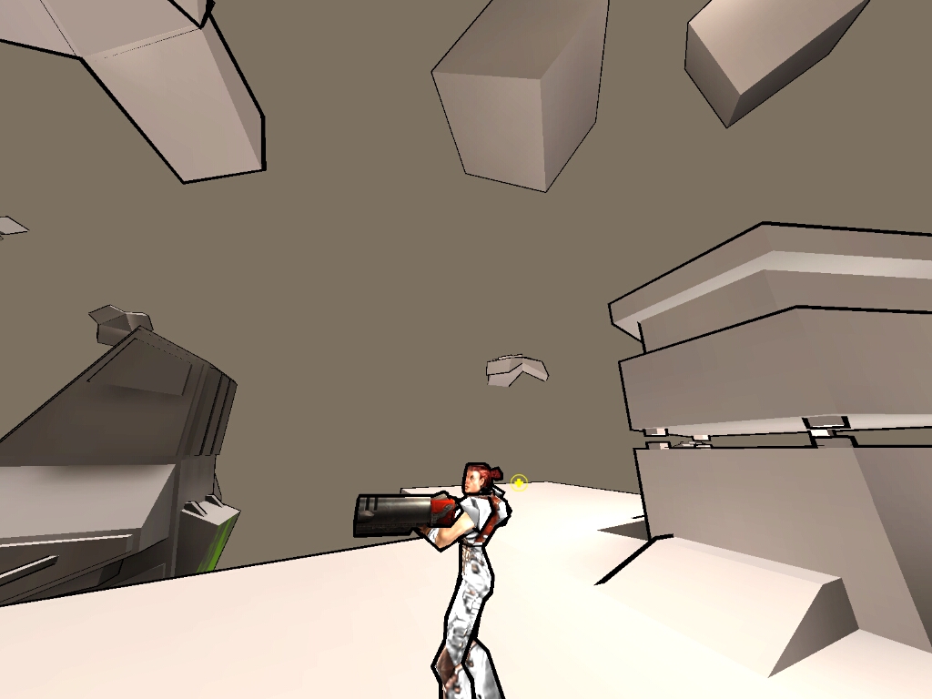
What I want - varying line thickness with intrusive lines inside the silhouette...
enter image description here

What I don't want...

enter image description here


EDIT: Further research has turned up the following...

Since I have a massive vertex count on terrain, even considering distance-based LoD, neither flipped-normals nor a geometry shader based approach (even with frustum culling) would be a sensible option due to sheer computational complexity involved in duplication & scaling of all uploaded vertices.

Considering that I don't need per-pixel lighting in the form of solid-tone shading on the terrain surfaces, it also becomes less prudent to consider any face-normal based approaches -- otherwise a requirement for correct surface lighting -- as these are naturally quite expensive to calculate. It is however true that they give the finest degree of control; for example, the ability to shade edges using "artistic" strokes: Beautiful, but again, not really viable for a massively complex game environment.

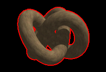
Stencil buffers are something I'd rather avoid as I'd prefer to do all work in shaders. (The above example with the red outline was done with a stencil buffer -- old school.)

This leaves fragment shader image-space approaches. Computational complexity is reduced to the number of fragments rather than the number of vertices (in my case, this is 10-100x fewer operations than I would have to do in the geometry shader). This requires more than one render pass in order to generate a g-buffer (consisting of a normal buffer and optionally a depth buffer as well) to which we can apply discontinuity filters (eg. Sobel operator). Depth discontinuity is what enables suggestive contours and creases. My only quibble with this approach is the inability to provide finer control over inked edge widths, though with the right algorithm in the fragment shader, I'm sure this would be possible.

So the question now becomes more specific: How exactly would I go about getting variable edge widths, particularly on the outer silhouette, in a fragment shader?

\$\endgroup\$
5
  • \$\begingroup\$ Varying line thickness is a feature of the geometric approach. Can't efficiently get it any other way. Since you want that, I don't see pixel shaders as being the "more efficient method": number of pixels to be searched = (line_thickness * 2 + 1) ^ 2 - 1. That would basically mean that your post-process shader will be a lot (guesstimate: 10x) slower if max. line width equals 2. Just drop pre-judging and try the geometry shader approach. \$\endgroup\$
    – snake5
    Commented Dec 4, 2012 at 14:07
  • \$\begingroup\$ @snake5 You're honestly suggesting that I run through 150 million vertices per render update (about 25 million with view culling), in the GS? I'm not really buying that, but thanks for the input. Refer back to what I stated above about vertex counts and complexity. Even with your 10x figure, the fragment shader would at least draw even, and probably do a hell of a lot better. \$\endgroup\$
    – Engineer
    Commented Dec 4, 2012 at 14:26
  • \$\begingroup\$ 25 million vertices (linear reads/writes) vs. 23 million texture samples (rather poorly cached memory reads + decompression of render target data) @ 1280x720. Limiting/reducing vertex count is a lot easier, by the way. Especially these days, when big monitors (1920x1080+) & multimonitor setups are getting very popular. \$\endgroup\$
    – snake5
    Commented Dec 4, 2012 at 15:02
  • \$\begingroup\$ what about using same algorithm as the one generating red outlines, and then thinning/growing lines based on their depth? \$\endgroup\$
    – Ali1S232
    Commented Dec 4, 2012 at 18:57
  • \$\begingroup\$ @Gajoo, As I was saying in the question, it's not just about the silhouette. Note the intrusive lines behind the girl's shoulder in the first image. Those are a function of the flipped-normals approach, and act as suggestive contours / creases. I need same. \$\endgroup\$
    – Engineer
    Commented Dec 4, 2012 at 19:03

2 Answers 2

4
\$\begingroup\$

I've decided to go with a fragment shader approach via discontinuity filtering of the depth buffer. Reasons for this are:

  1. World vertex count is very, very high due to immense view distances, even with mesh LoD;
  2. I am doing a number of other fragment shader operations, such as DoF blur which can benefit by the same structures (box or gaussian sampling/filtering) in the same pass.

Having tested it, I would say that in future projects I'd go for a geometry-based approach instead, for complexity reasons. The reason is that (as others suggested in the comments), fragment shader approaches to edge detection can be computationally intense, particularly with DoF implementations where the circle of confusion radius, and thus the number of samples per fragment, can be quite high. This is fortunately less of a concern for outline shaders.

\$\endgroup\$
2
  • \$\begingroup\$ I think going with normals discontinuity would give you better results in case you got flat normals. You can vary the line width by taking samples farther apart. \$\endgroup\$ Commented Dec 7, 2012 at 11:35
  • \$\begingroup\$ @Grieverheart This is the accepted answer, because the method I'm using works just fine. Thanks. \$\endgroup\$
    – Engineer
    Commented Dec 7, 2012 at 11:48
0
\$\begingroup\$

There is actually a very easy general solution if you can use an after effect. The great thing is, it doesn't matter how high your poly-count is. Render a Depth map as greyscale, then create a dot in the line color you want, when the contrast between two adjacent pixels is higher than a threshold value. You can make the dot bigger according to the contrast and or light-level of the image you rendered.

I invented the toonShader algorithm back in 2000/2001, even before that French dude, who created this solution. Mine was based on actual materials geometry. Then there are basically two ways to do it: 1. look at normals, if normals two planes connected to a line are facing away and towards the camera, render that line, you can then use depth, lighting etc as cues for linedepths. 2. Look at rendered geomerty (so after perspective transformation) Take each linesegment, if the vertices of the connecting planes are on the same side of this linesegment, you render the line.. You can then do the same for line-thickness as in method 1. 3. You could make combinations of these three techniques, but I mentioned the first, because you indicated a huge poly-count.

\$\endgroup\$

You must log in to answer this question.

Not the answer you're looking for? Browse other questions tagged .