I'm currently working on a Three.js project, and I'm aiming to create a seamless cube map. To achieve this, I created six planes and assembled them into a cube. Then, I utilized a shader to generate noise (these are not textures) on the cube's faces.
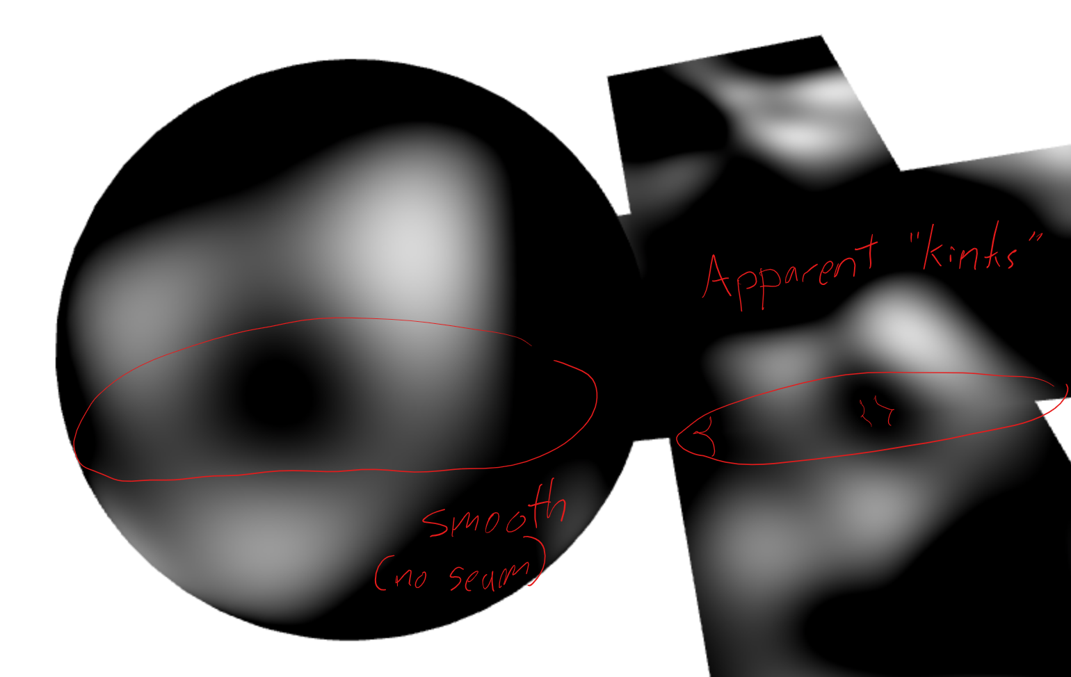
you can already see the distortion between the cube faces.
](https://i.sstatic.net/Dc9hJ.png)
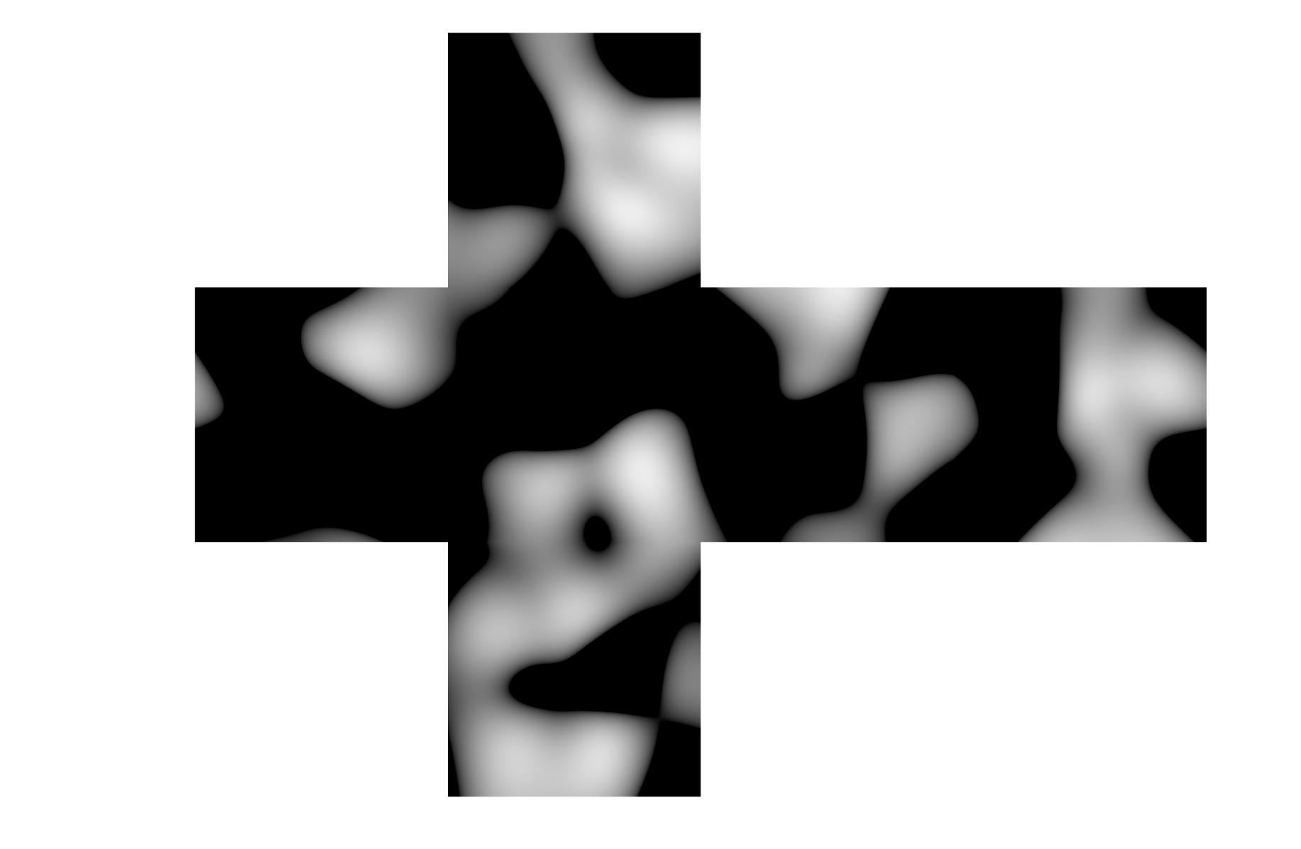
I also implemented a process in the shader to undo the transforms for each mesh, which effectively keeps the noise in place, resulting in a cube map-like object as you can see in the first image below.
At first glance, the cube map appears seamless,
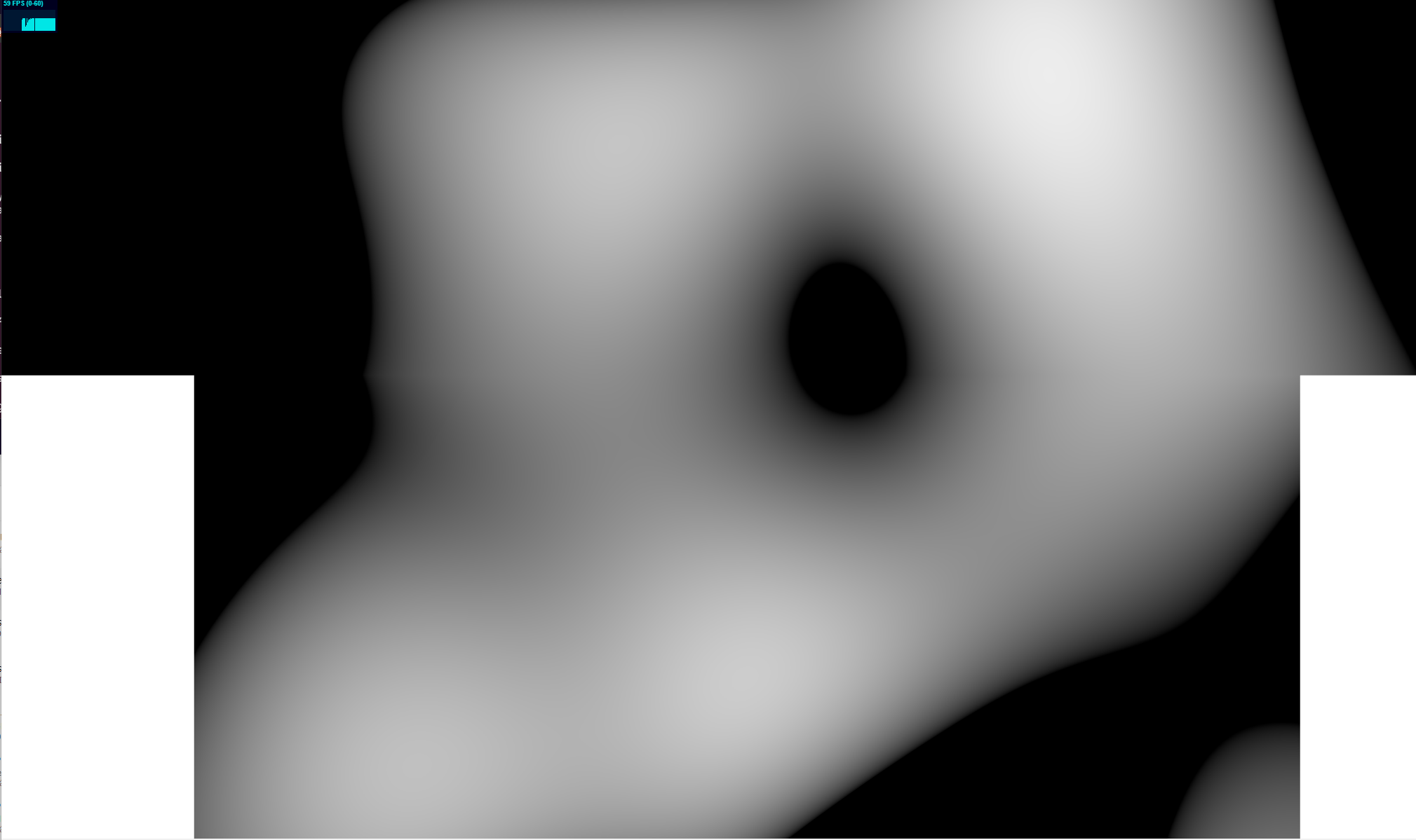
 but upon closer inspection, slight distortions are visible at the edges. This becomes a bigger issue when I attempt to convert it to a normal map, resulting in poor lighting. Regardless of the method I try, I always end up with seams where the edges of each face of the cube touch.
(front bottom edge and bottom top edge distortion):

zoomed-in look, you can see how to start to converge.

Any guidance or solutions to achieve a truly seamless cube map would be highly appreciated. I've looked through various resources, but I couldn't find a comprehensive explanation or tutorial specifically tailored to creating seamless cube maps in Three.js.
After doing some more research, when you get extremely close to a seam it appears that the meshes never actually touch (I don’t why I was under the assumption they did); they don’t share the same position at each face edge. Despite my efforts to position them as close as possible without overlapping, there remains a tiny space between the meshes, as indicated by the dotted white line.
I believe that the discontinuity is likely caused by the noise function lacking the necessary additional information to bridge this gap.

It took some time to put together but here is a working example of my code: EXAMPLE
let camera,scene,mesh,renderer


//-----------noise functions
function permute(){
  return  `
  vec4 permute(vec4 x){return mod(((x*34.0)+1.0)*x, 289.0);}
  `
 }
function taylorInvSqrt(){
return     `
    vec4 taylorInvSqrt(vec4 r){return 1.79284291400159 - 0.85373472095314 * r;}
    `
}
function snoise(){
return `
      float snoise3D(vec3 v){
        const vec2  C = vec2(1.0/6.0, 1.0/3.0) ;
        const vec4  D = vec4(0.0, 0.5, 1.0, 2.0);

        vec3 i  = floor(v + dot(v, C.yyy) );
        vec3 x0 =   v - i + dot(i, C.xxx) ;

        vec3 g = step(x0.yzx, x0.xyz);
        vec3 l = 1.0 - g;
        vec3 i1 = min( g.xyz, l.zxy );
        vec3 i2 = max( g.xyz, l.zxy );

        vec3 x1 = x0 - i1 + 1.0 * C.xxx;
        vec3 x2 = x0 - i2 + 2.0 * C.xxx;
        vec3 x3 = x0 - 1. + 3.0 * C.xxx;

        i = mod(i, 289.0 );
        vec4 p = permute( permute( permute(
                   i.z + vec4(0.0, i1.z, i2.z, 1.0 ))
                 + i.y + vec4(0.0, i1.y, i2.y, 1.0 ))
                 + i.x + vec4(0.0, i1.x, i2.x, 1.0 ));

        float n_ = 1.0/7.0;
        vec3  ns = n_ * D.wyz - D.xzx;

        vec4 j = p - 49.0 * floor(p * ns.z *ns.z);

        vec4 x_ = floor(j * ns.z);
        vec4 y_ = floor(j - 7.0 * x_ );

        vec4 x = x_ *ns.x + ns.yyyy;
        vec4 y = y_ *ns.x + ns.yyyy;
        vec4 h = 1.0 - abs(x) - abs(y);

        vec4 b0 = vec4( x.xy, y.xy );
        vec4 b1 = vec4( x.zw, y.zw );

        vec4 s0 = floor(b0)*2.0 + 1.0;
        vec4 s1 = floor(b1)*2.0 + 1.0;
        vec4 sh = -step(h, vec4(0.0));

        vec4 a0 = b0.xzyw + s0.xzyw*sh.xxyy ;
        vec4 a1 = b1.xzyw + s1.xzyw*sh.zzww ;

        vec3 p0 = vec3(a0.xy,h.x);
        vec3 p1 = vec3(a0.zw,h.y);
        vec3 p2 = vec3(a1.xy,h.z);
        vec3 p3 = vec3(a1.zw,h.w);

        vec4 norm = taylorInvSqrt(vec4(dot(p0,p0), dot(p1,p1), dot(p2, p2), dot(p3,p3)));
        p0 *= norm.x;
        p1 *= norm.y;
        p2 *= norm.z;
        p3 *= norm.w;

        vec4 m = max(0.6 - vec4(dot(x0,x0), dot(x1,x1), dot(x2,x2), dot(x3,x3)), 0.0);
        m = m * m;
        return 42.0 * dot( m*m, vec4( dot(p0,x0), dot(p1,x1),
                                      dot(p2,x2), dot(p3,x3) ) );
      }
      `
}

// -------- Create a custom shader
const vertexShader = `
varying vec4 worldPosition;
uniform  int ignoreFront; //<---- this is just a flag to ignore calling the undoTransfroms function for the front face
uniform  mat4 rm;
uniform  vec3 undoPoition;

vec3 undoTransfroms(vec3 v, mat4 rm){
  vec4 j =  (rm*vec4(v,1.));
  j.z += undoPoition.z;
  j.y += undoPoition.y;
  j.x += undoPoition.x;
  return j.xyz;
}

void main() {
    worldPosition = modelMatrix * vec4(position, 1.0);
    vec3 newPosition = position;
    if(ignoreFront == 1){
      newPosition = undoTransfroms( position,  rm);
    }
    gl_Position = projectionMatrix * modelViewMatrix * vec4(newPosition, 1.0);

}
`;

const fragmentShader = `
uniform vec3 center;
varying vec4 worldPosition;

${taylorInvSqrt()}
${permute()}
${snoise()}

void main() {
    float n = snoise3D(normalize(worldPosition.xyz-center));
    gl_FragColor = vec4(vec3(n), 1.0);
}
`;


//--------build mesh
function createPlaneMesh(x, y, z, rotationX, rotationY, rotationZ, uniforms) {
// Create a plane geometry
const planeGeometry = new THREE.PlaneGeometry(10, 10, 10, 10);
uniforms.center = {value:new THREE.Vector3(0,0,-5)}
const planeMaterial = new THREE.ShaderMaterial({
    uniforms: uniforms,
    vertexShader: vertexShader,
    fragmentShader: fragmentShader,
});
// Create the plane mesh
const planeMesh = new THREE.Mesh(planeGeometry, planeMaterial);
// Set the position of the mesh
planeMesh.position.set(x, y, z);
// Set the rotation of the mesh
planeMesh.rotation.set(rotationX, rotationY, rotationZ);
return planeMesh;
}
//------------


function init(){
//-----------Basic setUp
renderer = new THREE.WebGLRenderer( { antialias: true } );
renderer.setSize( window.innerWidth, window.innerHeight );
renderer.setAnimationLoop( animation );
document.body.appendChild( renderer.domElement );
renderer.setClearColor( 'white' )

camera = new THREE.PerspectiveCamera( 70, window.innerWidth / window.innerHeight, 0.01, 100 );
camera.position.z = 20;
var controls = new THREE.OrbitControls(camera, renderer.domElement);
scene = new THREE.Scene();

/********
- set creat mesh
- set transfroms
- set unifroms for undoing of transfoms
*********/
let widthHeight = 10

//------------front
let frontUnifrom = {ignoreFront:{value:0}}
let front = createPlaneMesh(0,0,0,0,0,0,frontUnifrom)
scene.add( front );
//-----------back
let bz    = -widthHeight
let bry   = Math.PI
var undorotationMatrix = new THREE.Matrix4();
undorotationMatrix.makeRotationY(-bry);
let backUnifrom = {rm:{value:undorotationMatrix},undoPoition:{value:new THREE.Vector3(bz*2,0,bz)},ignoreFront:{value:1}}
let back  = createPlaneMesh(0,0,bz,0,bry,0,backUnifrom)
scene.add( back );
//---------right
let rz    = -(widthHeight)/2;
let rx    =  (widthHeight)/2;
let rry   =  Math.PI/2;
var undorotationMatrix = new THREE.Matrix4();
undorotationMatrix.makeRotationY(-rry);
let rightUnifrom = {rm:{value:undorotationMatrix},undoPoition:{value:new THREE.Vector3(-rx,0,-rz)},ignoreFront:{value:1}}
let right = createPlaneMesh(rx,0,rz,0,rry,0,rightUnifrom)
scene.add( right );
//---------left
let lz    =  -(widthHeight)/2;
let lx    =  -(widthHeight)/2;
let lry   =  -Math.PI/2;
var undorotationMatrix = new THREE.Matrix4();
undorotationMatrix.makeRotationY(-lry);
let leftUnifrom = {rm:{value:undorotationMatrix},undoPoition:{value:new THREE.Vector3(-lx,0,-lz)},ignoreFront:{value:1}}
let left  = createPlaneMesh(lx,0,lz,0,lry,0,leftUnifrom)
scene.add( left );
//--------top
let tz    =  -(widthHeight)/2;
let ty    =  (widthHeight)/2;
let trx   =  -Math.PI/2;
var undorotationMatrix = new THREE.Matrix4();
undorotationMatrix.makeRotationX(-trx);
let topUnifrom = {rm:{value:undorotationMatrix},undoPoition:{value:new THREE.Vector3(0,-ty,-tz)},ignoreFront:{value:1}}
let top  = createPlaneMesh(0,ty,tz,trx,0,0,topUnifrom)
scene.add( top );
//---------bottom
let boz   =  -(widthHeight)/2;
let boy   =  -(widthHeight)/2;
let borx  =  Math.PI/2;
var undorotationMatrix = new THREE.Matrix4();
undorotationMatrix.makeRotationX(-borx);
let boUnifrom = {rm:{value:undorotationMatrix},undoPoition:{value:new THREE.Vector3(0,-boy,-boz)},ignoreFront:{value:1}}
let bo    = createPlaneMesh(0,boy,boz,borx,0,0,boUnifrom)
scene.add( bo );
}


// animation
init()

function animation( time ) {
    renderer.render( scene, camera );

}
<script src="https://cdn.jsdelivr.net/npm/[email protected]/build/three.min.js"></script> <script src="https://cdn.jsdelivr.net/npm/[email protected]/examples/js/controls/OrbitControls.js"></script> 

