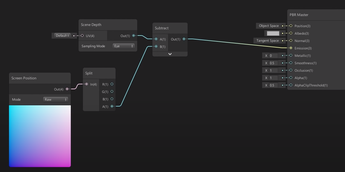
It sounds like when the Screen Position mode is in the "Raw" mode as used in the tutorial you linked, it's giving you the same result as you'd get from this shader...
struct v2f {
    float4 vertex : SV_POSITION;
    float4 screenPosition : TEXCOORD0;
}

v2f vert (appdata v) {
    v2f o;
    // This is effectively a multiplication by the Model-View-Projection matrix,
    // taking the vertex from object space to clip space (before the perspective divide)
    o.vertex = UnityObjectToClipPos(v.vertex);

    // This copies the information from the "special" vertex position semantic that in
    // older shader models we can't read directly in the fragment shader. Copying it out
    // lets us interpolate it and read it just like any other texture coordinate.
    o.screenPosition = o.vertex;
    return o;
}

fixed4 frag (v2f i) : SV_Target {
    // Here we get the per-pixel value, after it's been
    // interpolated between the three vertices in the triangle.
    float4 shift = i.screenPosition;

    // Ordinarily, 0,0 would be the center of the screen, but Unity calls
    // that mode "Center" not "Raw". In Raw mode, the center of the screen is 0.5
    shift.xy += 0.5f;
    return shift;
}
In this screenPosition value, the 4th component of the vector, "w" (or "Alpha / a" when you think of the vector as an RGBA colour), is the easiest to understand: it's the world-space depth of the pixel being drawn, measured from the camera, along its viewing axis. (Also called eye-space depth)
The x, y, and z components have been mangled by the projection in a way that makes them a bit more complicated to explain, so I'll attack them separately:
If we do "the perspective divide" on x and y, dividing them by the depth w, this brings them into normalized device coordinates, telling us where the pixel sits within our rendering viewport. x/w = -1 is the left edge, x/w = 0 is the center, and x/w = 1 is the right edge. Likewise for y/w along the vertical. The further away a point is in depth, the more it gets crunched-in by this perspective divide, creating the effect where objects appear smaller as they move further away.
The values before the division are related to the eye-space position of the point, scaled according to the horizontal and vertical field of view, and occasionally shifted if we're using an oblique frustum. Suffice it to say, they're "whatever we need them to be so that the perspective divide puts them into the right place on the screen" - it's usually not very meaningful to operate on these values before the division.
Note that in the Unity Shader graph node these x and y values have been shifted to keep (0.5, 0.5) at the center of the screen, presumably so that if you're using this to map a texture in screen space, it stays centered by default.
The z component has a different mangling applied, to handle clipping against the near and far planes, at z = -1 and z = 1 respectively. Values between these extremes are non-linearly distributed, and end up getting mapped to the values we use for depth-testing the fragment and ultimately writing into the depth buffer.
This non-linear z is useful for depth buffering, but not very intuitive for our purposes, which is why Unity includes macros and shader nodes that automatically decode it back to linear, world-space/eye-space depth for our convenience.
This node also has other modes:
Default: post perspective divide, and scaled/shifted so that x, y = (0, 0) is the bottom-left of the screen, (1, 1) is the top-right
Center: post-perspective divide, with no scale/shift, so x, y = (0, 0) is the center of the screen (-1, -1) is the bottom-left, and (1, 1) is the top-right
Tiled: like Center, but with the negative coordinates wrapped, so the values go from (0, 0) to (1, 1) over each quadrant of the screen.

