8
\$\begingroup\$

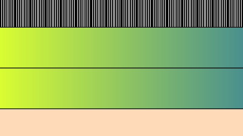
I'm seeing low quality bilinear texture sampling in WebGL, OpenGL and Directx, and was wondering if anyone knew how to make it higher quality? The picture below should help show what I mean.

The left uses the built in bilinear sampling, while on the right, i read in the 4 pixels of the texture and do linear interpolation myself, which results in a higher quality interpolation.

I've tried lots of things, including setting the precision to highp for everything, including the sampler, and also have tried using floating point textures and looking for any relevant extensions, but no luck.

Does anyone know if there's a way to get the smoother interpolation in WebGL?I have tried it on a couple different machines (all nvidia though) as well as the major browsers.

I know that I can make it higher quality by taking 4 samples and doing the bilinear interpolation myself, or by taking 2 samples where i left the hardware do the X axis, then i do the Y axis in my shader. Are there any other ways? Hopefully some solution that doesn't require more texture reads?

enter image description here

Here's a link to the actual WebGL page, where you can see the source: http://demofox.org/BilinearTest/bilineartest.html

Thanks for any help anyone can provide!!

EDIT: code details

I create a 2x2 texture with linear min and mag filters - no mips.

function createTexture(byteArrayWithRGBAData, width, height) {
    var texture = gl.createTexture();
    gl.bindTexture(gl.TEXTURE_2D, texture);
    gl.texImage2D(gl.TEXTURE_2D, 0, gl.RGBA, width, height, 0, gl.RGBA, gl.UNSIGNED_BYTE, new Uint8Array(byteArrayWithRGBAData));
    gl.texParameteri(gl.TEXTURE_2D, gl.TEXTURE_MAG_FILTER, gl.LINEAR);
    gl.texParameteri(gl.TEXTURE_2D, gl.TEXTURE_MIN_FILTER, gl.LINEAR);
    gl.bindTexture(gl.TEXTURE_2D, null);
    return texture;
}

....

var textureData = [
    128, 0, 0, 255,     50, 0, 0, 255,
     50, 0, 0, 255,    200, 0, 0, 255
];

// create the texture
theTexture = createTexture(
    textureData,
    2, 2
    );

I'm drawing a full screen quad, where the lower left has a texture coordinate of 0,0 and the upper right has one of (2,1). In my pixel shader, on the left side i sample along the diagonal of the image (again, using bilinear sampling), using the x texture coordinate to define where in the image 0.25 to 0.75 my u,v coordinates should be.

The left side uses bilinear sampling and you can see that it's very rough. This is the problem I'm trying to overcome, and have heard (but have not seen proof) that the texture is interpolated using 24.8 fixed point in the hardware, which makes those jaggies.

On the right side, i remap the 1.0-2.0 x axis texture coordinate to 0-1 so that it shows the same thing.

On the right side however, instead of doing hardware bilinear texture sampling, I'm getting the 4 pixels of the image and doing the bilinear interpolation in the fragment shader myself. The results are smooth like you'd expect, due to the calculations happening with floating point values.

To get the actual pixel color on both sides, i check the texture coordinate's y axis versus the pixel value interpolated. If the texture coordinate's y axis value is smaller, i make the pixel green, else make it black.

The vertex shader is uninteresting and just a pass through, but here's the fragment shader

<script id="shader-fs" type="x-shader/x-fragment">
precision mediump float;
uniform sampler2D uSampler;
varying vec2 vTextureCoord;

vec4 SamplePixel (vec2 pixel, bool bilinearSampling) {
    // Bilinear sampling:
    // Hardware based bilinear sampling
    if (bilinearSampling)
        return texture2D(uSampler, (pixel + vec2(0.5)) / 2.0);

    // Nearest sampling:
    // Software bilinear sampling (higher quality)
    float fracu = fract(pixel.x);
    float fracv = fract(pixel.y);

    vec2 floorPixel = floor(pixel) + vec2(0.5,0.5);

    vec4 A = texture2D(uSampler, floorPixel / 2.0);
    vec4 B = texture2D(uSampler, (floorPixel+vec2(1.0,0.0)) / 2.0);
    vec4 C = texture2D(uSampler, (floorPixel+vec2(0.0,1.0)) / 2.0);
    vec4 D = texture2D(uSampler, (floorPixel+vec2(1.0,1.0)) / 2.0);

    return mix(mix(A,B,fracu), mix(C,D,fracu), fracv);
}

void main(void) {
    vec4 colorValue;

    if (vTextureCoord.x < 0.995)
    {
        float pixel = vTextureCoord.x / 0.995;
        colorValue = SamplePixel(vec2(pixel), true);
    }
    else if (vTextureCoord.x > 1.005)
    {
        float pixel = fract(vTextureCoord.x - 0.005) / 0.995;
        colorValue = SamplePixel(vec2(pixel), false);
    }
    else
    {
        gl_FragColor = vec4(1.0);
        return;
    }

    float value = step(vTextureCoord.y, colorValue.x);
    gl_FragColor = vec4(0.0, value, 0.0, 1.0);
}
</script>
\$\endgroup\$
4
  • \$\begingroup\$ The OpenGL/OpenGL ES standard specifies the mathematical definition of GL_LINEAR sampling, but it does not specify a specific representation of the numbers involved. On my (AMD) hardware, it appears to do hardware linear filtering directly on UNSIGNED_BYTEs for GL_RGBA8 textures (not sure about sRGB, float, or higher precision normalized-integer formats), so the output of the filtering is still an 8 bit unsigned integer for each channel, which is then converted to a floating point vector, rather than converting all the surrounding pixels to floating point and doing the filtering there \$\endgroup\$
    – bcrist
    Commented Jun 13, 2015 at 21:35
  • \$\begingroup\$ @bcrist the strange thing is that if I switch to a floating point texture, it has the same precision issues. \$\endgroup\$
    – Alan Wolfe
    Commented Jun 13, 2015 at 22:10
  • \$\begingroup\$ I can't figure what is going on here. The output images have nothing to do with the array you claim is the texture. Neither output image looks like any form of filtering has been used. There are some way bigger problems than filtering. \$\endgroup\$ Commented Jun 14, 2015 at 11:31
  • \$\begingroup\$ The nice thing about webgl is that if you go to the link, it will run for you, and you can view and even modify the source. I'm not making any false claims and you can go see that for yourself. I think what has you confused is that I'm not just doing a texture sample, I'm doing logic with the result of a texture sample. Take a deeper look and you'll see what I mean. \$\endgroup\$
    – Alan Wolfe
    Commented Jun 14, 2015 at 14:00

2 Answers 2

5
+150
\$\begingroup\$

As luck would have it Iñigo Quilez wrote an article about this which popped up in my Facebook feed this morning.

Hardware texture intepolation is fast and convenient. It is bilinear (plus mipmapping), and despite it can be somehow improved, it works great for most cases. Most cases being texture mapping of surfaces with color/albedo, normal and specular textures. Generally these types of textures don't need lots of color fidelity (where "color" means pixel value/content), and therefore the hardware's texture interpolation units implement some simple interpolation based on 24.8 fixed point arithmetic. That's what all GPUs' hardware implments these days.

A 24.8 precision texture interpolator means that there's a maximum of 256 intemediate values possible between two adjacent pixels of a texture. 256 values are a lot for albedo textures for sure, but often in computer graphics textures encode not only surface properties, but they serve as LookUp Tables (LUT), heighfields (for terrain rendering), or who knows what. In those cases, you can find yourself easily lacking more resolution than 256 values between pixels.

Here's an example image from the article:

(Top) Hardware interpolation: visually smooth, but the barcode shows the derivative is spiky. Interpolation example from the article (Bottom) Manual interpolation: the constant colour in the derivative bar shows we're not getting step artifacts anymore.

So there's the answer. Hardware filtering is mainly intended to bridge sub-texel gaps for surface textures. So assuming our textures have enough resolution & mip maps for how close they are to the camera, we usually only have to interpolate a few steps - to deal with a texel center that's just a bit off from our rendered pixel center, or to fill a gap between two adjacent texels that are slightly more than 1 rendered pixel apart. For most cases, if we need anywhere near all 256 interpolation steps shown at once, it's because the player has crammed their camera right up against a wall, or we're trying to massively stretch a texture that's too low-res for the use it's being put to.

But if we're doing procedural graphics, it's often tempting to use a low-resolution texture stretched wide to give us low-frequency gradients, using the texture interpolator to give us free bilinear interpolation between samples. For colours this is often okay, since the human eye is pretty bad at spotting banding artifacts unless they're extreme. But if we care about the precise value at each sample - like for heightfields or sharp thresholds as you're doing here, then these staircase & plateau artifacts creep in.

So what can we do about it?

The most general-purpose solution (and what Iñigo Quilez recommends in his article) is exactly what you're doing: sample the texture four times and interpolate the results yourself in the shader, where you have full floating point precision.

If the case you've shown is representative of your real applications though, there may be more efficient methods:

  • Increase the resolution of your input texture, say to 16x16. Now the texture interpolation from a single fetch only needs to cover 1/15th as much ground with its 256 intermediate values, so you have an effective range of 3840 intermediates from one edge to the other. Much better! And still with only 1 texture sample. The memory taken up by this texture is still tiny, so you needn't feel bad about being wasteful.

  • If you only ever need to do bilinear filtering between the same 4 corners, you might as well do away with the texture and do it all in shader variables. This way you don't pay for even a single texture fetch. You can profile to double-check, but I'd wager this might be even be faster than using the "free" interpolation from the texture pipeline, since there's no contention or caching overhead.

\$\endgroup\$
6
  • \$\begingroup\$ IQ is amazing isn't he? (: Very high quality answer but unfortunately, I've seen this already and it doesn't help my situation. I'm trying specifically to not have to do more texture reads, and also unfortunately I really do need these specific values between these 4 pixels (I'm using bilinear sampling to do bilinear interpolation of data stored in a texture). My hope is that there's some extension, or alternate texture format that will actually give me better results. I'm hoping for a different answer, but will accept yours if none come :P \$\endgroup\$
    – Alan Wolfe
    Commented Jun 14, 2015 at 14:31
  • \$\begingroup\$ Also i wanted to mention, there is an alternate method i mention in my question that also works well but takes 2 texture reads (instead of the 1 or the 4). You can modify your texture coordinates and do two reads such that it gives you back two linear filtered (not bilinear filtered) samples that have been lerped across the x axis, then you can do the y axis mix in the fragment shader. It's not as good as reading all 4 in, but it is better than just doing the 1 read! \$\endgroup\$
    – Alan Wolfe
    Commented Jun 14, 2015 at 14:33
  • \$\begingroup\$ Oh also... I'd prefer not to canabalize the other color channels to get higher precision. Ideally i'd do one texture read and get 4 smoothly interpolated values. Figured that suggestion might be coming next so pre-emptively mentioning that (; Thanks again for the nice response man. \$\endgroup\$
    – Alan Wolfe
    Commented Jun 14, 2015 at 14:42
  • 1
    \$\begingroup\$ @AlanWolfe "the hardware's texture interpolation units implement some simple interpolation based on 24.8 fixed point arithmetic. That's what all GPUs' hardware implments these days" In other words, unless you want to design your own GPU from the ground up, you're going to be stuck with this behavior. Your 2 texture reads method would result in a smooth d/dy, but the d/dx would still be plagued by discontinuities. \$\endgroup\$
    – bcrist
    Commented Jun 14, 2015 at 17:33
  • 1
    \$\begingroup\$ Sorry, no I don't. In any case, even if NV/AMD/Intel did go on the record about this kind of thing, it doesn't preclude the possibility of things changing when new architectures are produced. The only way to "prove" it is to observe the behavior on a variety of hardware from different manufacturers. \$\endgroup\$
    – bcrist
    Commented Jun 14, 2015 at 17:42
1
\$\begingroup\$

I found this paper:
"Efficient GPU-Based Texture Interpolation using Uniform B-Splines" http://www.mate.tue.nl/mate/pdfs/10318.pdf

Which states:

It should be noted that there are some precision issues associated with the hard-wired linear texture interpolation. When, e.g.,an eight-bit texture is filtered, most people would expect that first the neighboring texture knots are queried, casted to floating point, and then weighted and added. This is, however, not the case; the texture knots are first weighted and added, and then casted to floating point, which limits the precision to the least significant bit of the texture data format [Ruijters et al. 08], as is illustrated in Figure 4. As a consequence, higher accuracies can only be obtained by using larger texture words, and thus at the cost of texture memory consumption.

A further precision issue of the linear texture interpolation is caused by the fact that the accuracy of the texture coordinates is limited to a fixed-point format with eight bits of fractional value [NVIDIA 08]. This means that there are only 254 discrete coordinate positions between two texture knots, as shown in the zoomed graph in Figure 4, which is especially of interest when the knots are far apart...

The two references it has are:

[NVIDIA 08] NVIDIA Corporation. “Linear Filetering.” In NVIDIA CUDA Compute Unified Device Architecture: Programming Guide, Appendix D.2, 2008. http://www.uni-graz.at/~liebma/CUDA/NVIDIA_CUDA_Programming_Guide_2.0.pdf

and:

[Ruijters et al. 08] Daniel Ruijters, Bart M. ter Haar Romeny, and Paul Suetens. “Accuracy of GPU-based B-Spline Evaluation.” In Computer Graphics and Imaging (CGIM), pp. 117–122. Calgary, AB, Canada: ACTA Press, 2008. http://www.dannyruijters.nl/docs/GPU_AccuracyBSpline.pdf

\$\endgroup\$

You must log in to answer this question.

Not the answer you're looking for? Browse other questions tagged .