I'm creating a procedurally generated planet mesh based on quadtree splitting to support LOD system. I cannot find any relevant info how can I calculate distance between the camera and LOD chunks.
I have a surface view in my game where the camera is near at the planet surface and can move around the planet, it has also some zoom levels (elevation of the camera) but camera always looks in the direction to the surface like in strategy games.
A: Should I use simple distance calculation between the camera and the center of the chunk mesh or edge vertices of the mesh?
B: Is it better when I use Great-circle distance?
C: How should I modify the calculation when camera's elevation can be changed?
D: How can I determine the distance limits for each LOD level? Does it depend on the project or does it have some basics?
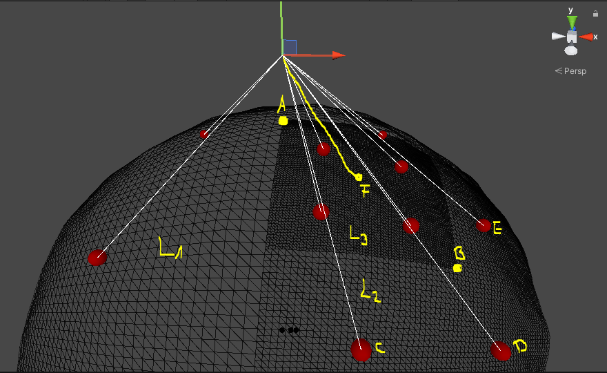
Update #1: Here is a sample when I use simple distance calculation between the center vertex of the meshes and the camera object:
- the camera is right above the point A
- point A is the center of the level 0 mesh (it is not visible because it is already divided)
- when the camera reaches the distance limit of B (which is a level 1 mesh and it is already divided in the sample) then it will be divided into four meshes where the centers are C, D, E, F
- at this time the mesh where the center point is F will be also divided because the distance of the previously generated F point is under the current LOD level minimum distance
So the base problem this: after dividing a mesh the new submeshes can be also divided because the distance is under the current LOD level minimum distance. And I think it does not work like a normal LOD system because there is a level 1 neighbour next to level 3 mesh.
Update #2: I tried some approaches to get the right distance calculation:
- minimum distance between the corner edges (4) and the camera
- minimum distance between the edge center vertices (4) and the camera
- minimum distance between the corner and edge center vertices (8) and the camera
Important thing: I use great-circle distance calculation.
I got wrong results using these until I created a new algorithm to define transition distance limits. Maybe it is not a very well algorithm but currently this is the most acceptable result. Here is the algorithm:
Note: ignore the heightmap (noise) during the calculation, only a simple sphere with radius R is used
- calculate the width of each meshes (arc length)
- decrease the distance limit in each LOD level
float meshSphericalWidth = 2 * Mathf.PI * _shapeGenerator.Radius * (90 / (float)(CurrentLevelOfDetail + 1) / 360f);
float currentTransitionLimit = meshSphericalWidth * Mathf.Pow(0.90f, CurrentLevelOfDetail + 1);
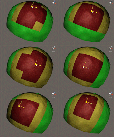
After this distance calculation change I didn't notice any significant difference when I use the corner or the edge vertices to get the minimum distance. And I got this. Green is LOD1, yellow is LOD2 and red is LOD3.
It seems a good progress but we can see sometimes between two chunks the LOD level difference is 2.
Can I fix it with another distance calculation adjustments or is it a different story? I want to solve the cracks between meshes.


