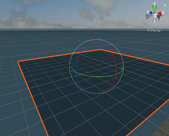
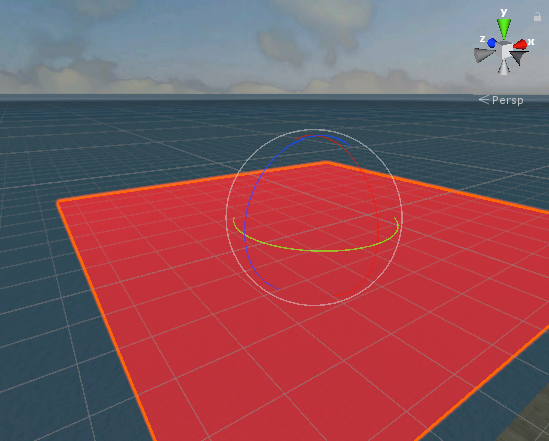
I am trying to show both sides of a mesh. I understand this question has been asked a lot, but all of the answers I've found seem like they're written for Unity 5 and I can't find a "Cull" setting on the shader.
Beyond that, I'm actually okay with extending the mesh to render both sides. In what I've read online, this may actually be the "correct" way to do it in that this should get all the lighting, shadows, etc. to render correctly.
My issue is that, when I make a mesh face two different directions, it's like the materials collide and I get a black appearance instead of the material I'm expecting:
The bottom is what I expect to see, but the top is what I'm getting when I render both faces.
To recreate, create an empty game object. Add a MeshRenderer and a MeshFilter, then add the TestMesh script:
using System.Collections;
using System.Collections.Generic;
using UnityEngine;

public class TestMesh : MonoBehaviour
{
    public float width = 1f;
    public float length = 1f;
    public bool showPlane = true;

    private void OnValidate()
    {
        if(showPlane)
        {
            MeshRenderer rendObj = gameObject.GetComponent<MeshRenderer>();
            MeshFilter meshObj = gameObject.GetComponent<MeshFilter>();
            if((rendObj==null)||(meshObj==null))
            {
                Debug.LogErrorFormat("Error - TestMesh: MeshRenderers and MeshFilters need to be added to {0}", gameObject.ToString());
                return;
            }
            Mesh testMesh = meshObj.sharedMesh;
            testMesh.Clear();
            CreateMesh(testMesh);
        }
    }

    private void CreateMesh(Mesh mesh)
    {
        float x = 0.5f * width;
        float y = 0f;
        float z = 0.5f * length;

        Vector3 origin = Vector3.zero;

        // Make the corners of the plane
        Vector3 corner1 = new Vector3( x, y,  z);
        Vector3 corner2 = new Vector3( x, y, -z);
        Vector3 corner3 = new Vector3(-x, y, -z);
        Vector3 corner4 = new Vector3(-x, y,  z);

        // Rotate them to whatever the orientation of the gameObject is
        corner1 = gameObject.transform.rotation * corner1;
        corner2 = gameObject.transform.rotation * corner2;
        corner3 = gameObject.transform.rotation * corner3;
        corner4 = gameObject.transform.rotation * corner4;

        // Make them into a list for easy iteration
        List<Vector3> corners = new List<Vector3>(new Vector3[] { corner1, corner2, corner3, corner4, corner1}); // Add corner1 again at the end to close the loop

        // Initialize the vertices, uvs, and triangles lists
        List<Vector3> vertices = new List<Vector3>();
        List<Vector2> uvs = new List<Vector2>();
        List<int> triangles = new List<int>();

        // vertices[0] is the origin of the plane, and the plane is comprised of four triangles.
        vertices.Add(origin);
        uvs.Add(Vector3.zero);

        // Add the first corner to the vertices list, so now vertices[1] = corner1
        vertices.Add(corners[0]);
        uvs.Add(new Vector2(corners[0].x, corners[0].z));

        // Loop through the remainder of the corners
        for (int i=1; i<corners.Count; i++)
        {
            vertices.Add(corners[i]);
            uvs.Add(new Vector2(corners[i].x, corners[i].z));

            triangles.Add(0); // Each triangle starts at the origin and links two corners
            triangles.Add(i); // What you're doing here is linking a vertex of a triangle to an entry in the triangles list
            triangles.Add(i + 1); // Adding 0 means you want the first vertex to be vertices[0] - the origin. Adding [i] means
                                  // you want cornerI, because remember that vertices[0] is origin, so vertices[1] is corner1,
                                  // vertices[2] is corner2, etc.


            triangles.Add(0);       //
            triangles.Add(i + 1);   //   <------- HERE IS THE TROUBLE
            triangles.Add(i);       //
                                    // I would have thought I can add the vertices in reverse order to flip the auto-calculated face normal, but
                                    // what I'm getting is a black material where it looks like maybe I'm seeing a doubling of the material even though
                                    // I should only see one face.

        }

        // Convert the lists to arrays and send them to the mesh.
        mesh.vertices = vertices.ToArray();
        mesh.uv = uvs.ToArray();
        mesh.triangles = triangles.ToArray();
        mesh.RecalculateNormals();
    }
}
You can use any material if you want, but here's the .mat file for the laser material I've got (it's a generic material that's slightly transparent and red):
%YAML 1.1
%TAG !u! tag:unity3d.com,2011:
--- !u!21 &2100000
Material:
  serializedVersion: 6
  m_ObjectHideFlags: 0
  m_CorrespondingSourceObject: {fileID: 0}
  m_PrefabInstance: {fileID: 0}
  m_PrefabAsset: {fileID: 0}
  m_Name: LaserPlane
  m_Shader: {fileID: 46, guid: 0000000000000000f000000000000000, type: 0}
  m_ShaderKeywords: _GLOSSYREFLECTIONS_OFF _SPECULARHIGHLIGHTS_OFF
  m_LightmapFlags: 4
  m_EnableInstancingVariants: 0
  m_DoubleSidedGI: 1
  m_CustomRenderQueue: -1
  stringTagMap: {}
  disabledShaderPasses: []
  m_SavedProperties:
    serializedVersion: 3
    m_TexEnvs:
    - _BumpMap:
        m_Texture: {fileID: 0}
        m_Scale: {x: 1, y: 1}
        m_Offset: {x: 0, y: 0}
    - _DetailAlbedoMap:
        m_Texture: {fileID: 0}
        m_Scale: {x: 1, y: 1}
        m_Offset: {x: 0, y: 0}
    - _DetailMask:
        m_Texture: {fileID: 0}
        m_Scale: {x: 1, y: 1}
        m_Offset: {x: 0, y: 0}
    - _DetailNormalMap:
        m_Texture: {fileID: 0}
        m_Scale: {x: 1, y: 1}
        m_Offset: {x: 0, y: 0}
    - _EmissionMap:
        m_Texture: {fileID: 0}
        m_Scale: {x: 1, y: 1}
        m_Offset: {x: 0, y: 0}
    - _MainTex:
        m_Texture: {fileID: 0}
        m_Scale: {x: 1, y: 1}
        m_Offset: {x: 0, y: 0}
    - _MetallicGlossMap:
        m_Texture: {fileID: 0}
        m_Scale: {x: 1, y: 1}
        m_Offset: {x: 0, y: 0}
    - _OcclusionMap:
        m_Texture: {fileID: 0}
        m_Scale: {x: 1, y: 1}
        m_Offset: {x: 0, y: 0}
    - _ParallaxMap:
        m_Texture: {fileID: 0}
        m_Scale: {x: 1, y: 1}
        m_Offset: {x: 0, y: 0}
    m_Floats:
    - _BumpScale: 1
    - _Cutoff: 0.5
    - _DetailNormalMapScale: 1
    - _DstBlend: 0
    - _GlossMapScale: 1
    - _Glossiness: 0
    - _GlossyReflections: 0
    - _Metallic: 0
    - _Mode: 0
    - _OcclusionStrength: 1
    - _Parallax: 0.02
    - _SmoothnessTextureChannel: 0
    - _SpecularHighlights: 0
    - _SrcBlend: 1
    - _UVSec: 0
    - _ZWrite: 1
    m_Colors:
    - _Color: {r: 1, g: 0.027406208, b: 0, a: 0.58431375}
    - _EmissionColor: {r: 257.00394, g: 0, b: 0, a: 1}
All I'm doing is flipping the order of the triangles, so I do
triangles.Add(0);
triangles.Add(1);
triangles.Add(2);
to make the forward-facing triangle and then do:
triangles.Add(0);
triangles.Add(2);
triangles.Add(1);
to make the backwards-facing triangle.
Again, I would expect each to get culled appropriately such that all I see is the correctly rendered material, but that's not happening. I've tried all kinds of settings in the material, but I can't find a cull setting (not that I want to go that route anyways) and I can't find anything that gets the material to render correctly.


forloop in the CreateMesh method. It results in this weird overlap (first image in the post) that ruins the material appearance. The material I'm using has transparency, so it looks kind of like a shadow, but non-transparent materials show up solid black. If I comment out either triangle triplet the other renders as expected, I just can't seem to do both and I don't know if it's a bug or if I'm doing something wrong. \$\endgroup\$