10
\$\begingroup\$

Assume I have a physics primitive I am going to call a "wire", wrapped around a 2D environment (as described in this question).

Here's an illustration of what that might look like:
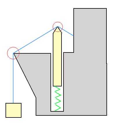
wire wrapped around static and dynamic game objects

In the example illustration: The box is being pulled upwards (held up) by the wire, and the box is pulling the wire downwards. The object on the spring is being pushed downward by the wire, but is also pushing the wire upwards.

While I haven't figured out how to implement it yet, assume the wire will slide freely across the points that it is wrapped around.

In a 2D physics simulation (ie: frame based) how do you calculate the forces (or impulses) to apply to the objects that are attached to or wrapped by a wire like this?


As I alluded to in my first question, I imagine that if the only non-static object "on" the wire was the mass at the end, then the force would be identical to a fixed-length joint between the mass and the point before that on the wire.

\$\endgroup\$

3 Answers 3

9
\$\begingroup\$

The box pulling on the wire applies a tension to the wire. Tension is a force, measured in Newtons. If we make some simplifying assumptions (no friction between wire and environment) then the tension is the same at all points along the wire.

If we consider your example to be static, then the tension on the wire is just the weight of the box:

T = m * g

where m is the mass of the box and g is acceleration due to gravity (i.e. 9.8 m/s^2). Note this is only valid in the static case, see below for an explanation of how to calculate it in the dynamic case.

The force at each bend in the wire is then just the projection of the tension onto the relevant direction. For example the force at the tip of the spring object is a force along the contact normal, of magnitude:

F = T * cos(angle between wire and contact normal)

In this case the contact normal direction would be the bisection of the angle between the wire segments. The force at your second marked point on the environment is irrelevant, since it has no impact on the tension or anything else.

Now, in the dynamic case the tension is simply the constraint force which you apply to the box in order to keep it attached to the wire. So if the physics engine is impulse based, the tension is just:

T = impulse / timestep

This leads into the general algorithm for wrapping the wire around the environment too. The important property is the total length of the wire. Only the last segment needs to be simulated, all the earlier segments can be considered to be fixed. So the length of the last segment is known, just subtract the lengths of the earlier segments from the total length. Then the last segment can be a simple spring constraint. Then just split a segment whenever it intersects with the environment, and remove the split when the bend straightens out.

\$\endgroup\$
3
  • \$\begingroup\$ So - just to clarify: I would have the free mass on a fixed-length joint which attaches to the world at the next "bend" in the wire. I find out what impulse that joint applies to the box each frame, and from there I can get the tension in the wire? \$\endgroup\$ Commented Jul 23, 2010 at 7:09
  • \$\begingroup\$ Also - I am concerned about F = T * cos(angle between wire and spring axis). Which angle, exactly? Also: I don't think that (in the simulation) there is a sensible way to have the wire "know" that there is a spring attached to that object. \$\endgroup\$ Commented Jul 23, 2010 at 7:17
  • \$\begingroup\$ @Andrew - For your first point, yes, the force applied to the box by the joint is by definition equal to the tension in the wire. For your second point, you're right, this wasn't very clear, it's actually the angle between the wire and the contact point normal. I've edited the answer to make this clearer. \$\endgroup\$
    – Niall
    Commented Jul 23, 2010 at 7:38
4
\$\begingroup\$

I definitely appreciate your frustration in these wire-based threads, it's a hard problem to solve. We never got collision working perfectly, but the constraint simulation is definitely doable and straightforward.

A wire constraint is actually almost identical to a regular distance constraint. Instead of two constraint points you have n+1 for a wire with n segments, one for each vertex -- at the end points the Jacobian is identical to a distance constraint (i.e it's something like d/|d| where d is the vector between points), and for the internal nodes the Jacobian is something like (a/|a| - b/|b|) where a and b are the vectors from the node to the adjacent nodes. (Sorry, it's been a couple years since I touched this...)

You can't fake it a-la "only the last segment is dynamic" because, as in your example, objects can interact with other segments, but you only need to simulate masses at the ends of the rope -- internally the rope can be massless. The constraint impulses calculated at each node need to be applied to the object that's colliding at that node.

Here are a few related papers:

The first three are relatively recent and should help a lot. Page 75 of the bottom paper describes a "multibar" constraint which is essentially a wire.

Good luck :)

raigan

\$\endgroup\$
0
\$\begingroup\$

The basic idea is that the length of the rope remains the same. If it's being pushed up, you will need to create a "split point" there. Then the rope determines on which side it's attached, because it can't "grow" in that direction. Because it's attached to something on the right, the piece of rope on the left will become shorter and the piece between the split point and the attached point will become slightly longer. Then, like Niall said, calculate the tension of the wire. How I would do this is to calculate the tension of each "piece" of rope. You can then use this to determine the forces involved.

Hope this helps.

\$\endgroup\$
1
  • \$\begingroup\$ Not really, sorry. \$\endgroup\$ Commented Jul 23, 2010 at 7:03

You must log in to answer this question.

Not the answer you're looking for? Browse other questions tagged .