2
\$\begingroup\$

I'm trying to draw a quad with a texture onto the screen such that texels and pixels perfectly align. Sounds pretty easy. I draw 2 triangles (as TRIANGLE_LIST, so 6 vertices) using these shaders:

struct VSOutput
{
    float4 position     : SV_POSITION;
    float2 uv           : TEXCOORD0;
};

VSOutput VS_Draw(uint index : SV_VertexId)
{
    uint vertexIndex = index % 6;
    // compute face in [0,0]-[1,1] space
    float2 vertex = 0;
    switch (vertexIndex)
    {
        case 0: vertex = float2(0, 0);  break;
        case 1: vertex = float2(1, 0);  break;
        case 2: vertex = float2(0, 1);  break;
        case 3: vertex = float2(0, 1);  break;
        case 4: vertex = float2(1, 0);  break;
        case 5: vertex = float2(1, 1);  break;
    }
    // compute uv
    float2 uv = vertex;
    // scale to size
    vertex = vertex * (float2)outputSize;
    vertex = vertex + topLeftPos;
    // convert to screen space
    VSOutput output;
    output.position = float4(vertex / (float2)outputSize * float2(2.0f, -2.0f) + float2(-1.0f, 1.0f), 0, 1);
    output.uv = uv;
    return output;
}

float4 PS_Draw(VSOutput input) : SV_TARGET
{
    uint2 pixelPos = (uint2)(input.uv * (float2)outputSize);
    // output checker of 4x4
    return (((pixelPos.x >> 2) & 1) ^ ((pixelPos.y >> 2) & 1) != 0) ? float4(0, 1, 1, 0) : float4(1, 1, 0, 0);
}

where outputSize and topLeftPos are constants and expressed in pixel units.

Now for outputSize = (102,12) and topLeftPos = (0,0) I get (what I would expect):

Output for x=0, y=0

But for outputSize = (102,12) and topLeftPos = (0,0.5) I get:

Output for x=0, y=0.5

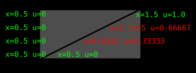
As you can see there is a uv-discontinuity where the two triangles connect and interpolation of uv is inaccurate. This basically happens (in x and y) only at positions around the .5 (actually below .49 it correctly snaps to texel 0 and above .51 it snaps correctly to texel 1, but in between I get this artifact).

Now for the purpose I need this for it is essential to have pixel perfect mapping. Can anyone enlighten me why this happens?

\$\endgroup\$

1 Answer 1

2
\$\begingroup\$

In theory it should not happen but because of the way the GPU rasterizes triangle lines there are some rounding errors on this particular GPU that differ between the texture coordinates and the pixel coordinates.

Texture coordinates does not use the same precision as the vertex coordinates, add to this perspective correction (even though the triangles are flat on screen) plus the way float numbers work and you get those pixel wiggles.

It could also be a loss of precision or difference in precision in the GPU's sub-pixel accuracy calculation of both vertex and texture coordinates.

enter image description here

Different GPUs and drivers will give different results.

Try changing the output.position line by adding floor() :

output.position = float4(floor(vertex) / (float2)outputSize * float2(2.0f, -2.0f) + float2(-1.0f, 1.0f), 0, 1));

This will remove the fractions of pixels and fix the rounding errors on most GPU/Drivers.

\$\endgroup\$
13
  • \$\begingroup\$ Well, but even if it would be a precision problem, I don't see how starting from equal positions and uvs it can result in a shearing of the texture. it may be shifted by pixels, but equally everywhere - so no shearing is to be expected. \$\endgroup\$
    – XorTdsc
    Commented Jan 13, 2015 at 17:59
  • \$\begingroup\$ i cannot really use the floor idea, because in the final shader, the quad can be rotated. basically i wanna make sure that the texel ends up on a pixel which is closest to the manually transformed corrdinate for that texel. I use it for a sort of hashing, so i can render all objects and then lookup for each texel the corresponding pixel which other texels share this pixel. \$\endgroup\$
    – XorTdsc
    Commented Jan 13, 2015 at 18:01
  • \$\begingroup\$ You can rotate the quad and still round its vertices down to pixel integers. Or you can use 2 shaders, one for non-rotated quads and one for rotated. You won't see a tear when the quad is rotated as everything will be unaligned. The other way to fix this that will prevent any tear is to use a single oversized triangle to draw the rectangle with a transparent area but this will make the GPU render twice as much (half of it will be transparent) and might still end up cut in parts inside the GPU when clipped by the screen boundaries. \$\endgroup\$ Commented Jan 13, 2015 at 19:56
  • \$\begingroup\$ There is shearing because of the diagonal split where 2 triangles make 1 rectangle. The interpolation of the diagonal has fractions of pixels. Pixel coordinates get interpolated one way in the GPU and texture coordinates get interpolated by a different system inside the GPU. This causes the tear you see due to rounding difference in both interpolations. \$\endgroup\$ Commented Jan 13, 2015 at 20:01
  • \$\begingroup\$ When rotating the vertices and rounding them to nearest int that will corrupt any subpixel correctness so that's not an option. I would have thought that the interpolation of uv works by computing gradients in x and y direction (in whatever precision) and using these to interpolate. These gradients should be the same for both triangles, so it's not entirely clear why that shearing artifact arises. I can try the suggested single triangle version, though. Maybe that helps. \$\endgroup\$
    – XorTdsc
    Commented Jan 14, 2015 at 10:55

You must log in to answer this question.

Not the answer you're looking for? Browse other questions tagged .