I have researched this a lot and so far all the examples, tutorials etc always use the following order: Scale * Rotate * Translate but for some reason this order must always be backwards in my Scene Graph. I am not sure if this is intended due to transforming local matrix to world matrix or it is an inherent bug in my application.
Here is my simple Scene Graph implementation. I am using Vulkan and GLM math library.
void SceneNode::setTransform(glm::mat4 transform) {
  transformLocal = transform;
}

void SceneNode::update() {
  // if root node
  if (parentNode == nullptr) {
    transformWorld = transformLocal;
  } else {
    transformWorld = parent->transformWorld * transformLocal;
  }

  for (auto &node : children) {
    node->update();
  }
}
And my shader logic:
// initialization code hidden for simplicity

void main() {
  // worldTransform = transform matrix calculated during scene node update
  gl_Position = UniformCameraData.projectionView * ModelPushConstants.worldTransform * vec4(vPosition, 1.0f);

  outColor = vColor;
}
As a demo, I have created a super simple scene with spheres:
Root
  Sphere Center -> Rotate around its own axis
    Sphere 1 -> Position somewhere near the parent and Rotate around its own axis
    Sphere 2 -> Position somewhere near the parent andRotate around its own axis
    Sphere 2 -> Position somewhere near the parent andRotate around its own axis
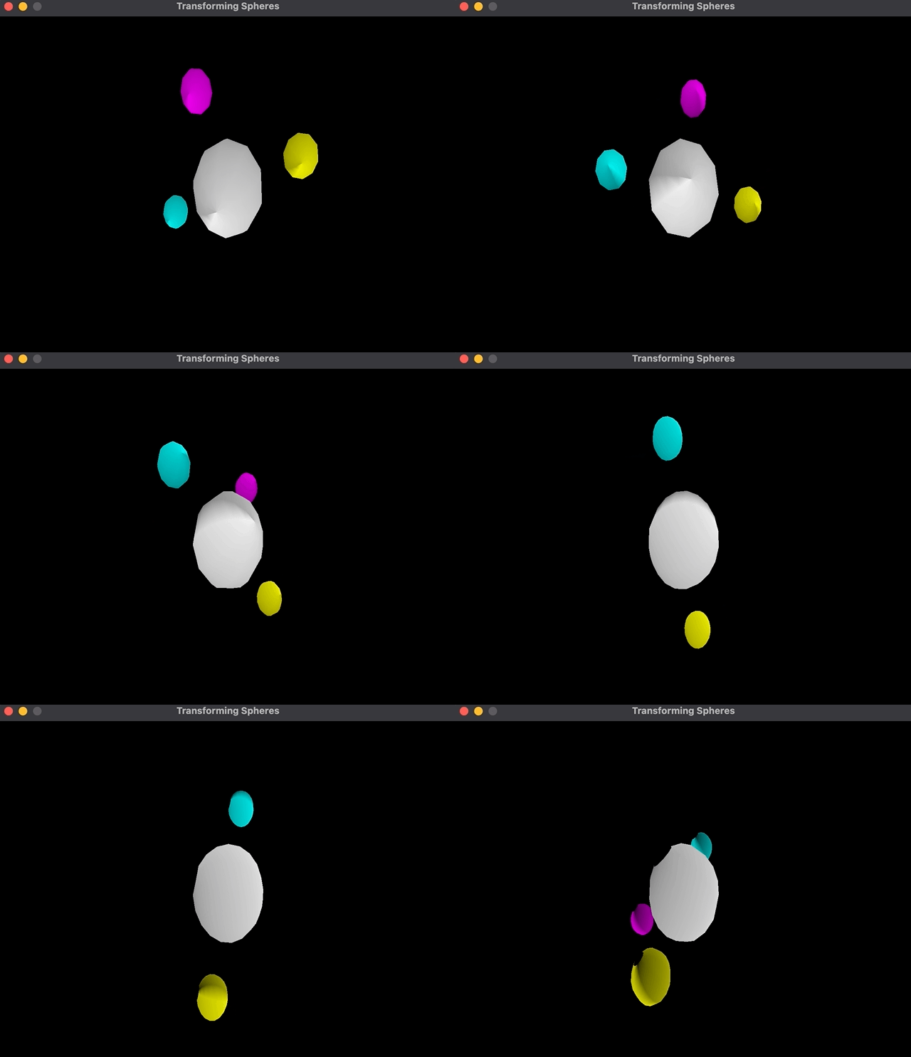
This scene graph gives me one sphere in the middle that rotates and three spheres that rotate due to being children of this sphere; plus, the spheres themselves rotate around their own axis:
However, the implementation of it is quiet weird to me. The order of transformations is Translate * Rotate * Scale instead of the other way around:
child1->setTransform(
          glm::translate(glm::mat4{1.0}, glm::vec3{2.0, 0.0, 0.0}) *
          glm::rotate(glm::mat4{1.0f}, glm::radians(frame * 0.9f),
                      glm::vec3{0.0, 0.0, -1.0}) *
          glm::scale(glm::mat4{1.0}, glm::vec3{0.4, 0.4, 0.4}));

// ...other children transformations

scene->update();
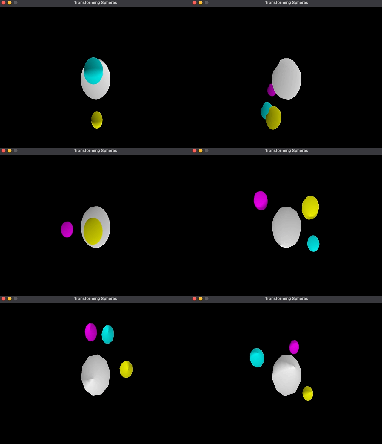
When I change the order of transformations, the rotation happens around the central sphere:
child1->setTransform(
          glm::rotate(glm::mat4{1.0f}, glm::radians(frame * 0.9f),
                      glm::vec3{0.0, 0.0, -1.0}) *
          glm::translate(glm::mat4{1.0}, glm::vec3{2.0, 0.0, 0.0}) *
          glm::scale(glm::mat4{1.0}, glm::vec3{0.4, 0.4, 0.4}));

// ...other children transformations

scene->update();
As you can see, the cyan color sphere rotates around the parent instead of its own center.
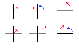
I was confused by this so, I added translation to the root node (e.g (2.0, 1.0)) and got the same result. If I rotate the sphere, then translate, it will rotate against (0, 0), then translate to (2.0, 1.0) at the same time, which will mean that it is at (2.0, 1.0) and rotating against (0.0, 0.0). On the other hand, if I translate first, then rotate, it will rotate against (2.0, 1.0) and translate to (2.0, 1.0) at the same time, which will mean that its rotating against the newly translated center.
Logically this makes sense to me because these multiplications are happening at the same time and the result is written to node but I still do not understand why the typically suggested transformation order is Scale * Rotate * Translate. Can someone explain to me what I am missing here that I have to use multiply transformations is in reverse order?


