0
\$\begingroup\$

I have a line segment joining two 3D points AB, and a vector V which is normal to it.

I need to know the angle of AB in the plane described with V as the plane normal, that is: in the plane of the two vectors (AB) and (AB cross-product V)

EDIT: Much more information... photo with doodles
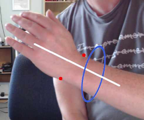
The points A and B (red dots) have x,y coordinates in the camera image, and an extrapolated depth (z) from the camera itself. The vector V (white line) is calculated from two more points with the same process. I have successfully matched rotation around the Z axis (camera view direction) so a (Unity) 3D object will track the wrist angle as it 'waves' (rotation in that single plane). Now I want to also include twisting motion defined as rotation around the wrist bone (blue ellipse attempting to represent rotation in a plane) like tipping a cup. This image is from a fixed webcam, but I would like the process to also work from a mobile phone (moving camera, with translation and rotation potentially) and one of my assumptions has been that if everything is camera relative via the screen projection, this will be automatically included.

By using a 'dumb as bricks' approach I have it working when the arm is horizontal... I can't work out how to make it work at other angles e.g. vertical:

            Vector3 AB = (B - A);
            return -Mathf.Atan2(AB.z, AB.y) * Mathf.Rad2Deg;

UPDATE3: This question now seems to have two parts:

  • what can I use as a fixed reference direction when the plane can be orientated in any direction?
  • how do I get an angle between that fixed reference and the line in that plane?

In searching I've come across both Rogrigues' Rotation Formula and this answer about rotating planes, but I haven't been able to work out how to apply either of them to this particular problem (I do feel like I'm missing a really obvious trick!)

Edit: My first idea is to rotate A and B so that V is aligned with the cartesian X axis and (ABxV) is aligned with Y, then use atan2(dy, dz). I have just started to look for a working solution to performing that rotation. Edit2: It's been pointed out referring to a cartesian X axis is ambiguous... I'm not sure but I think camera axis (horizontal/vertical in the image plane plus depth) might serve?

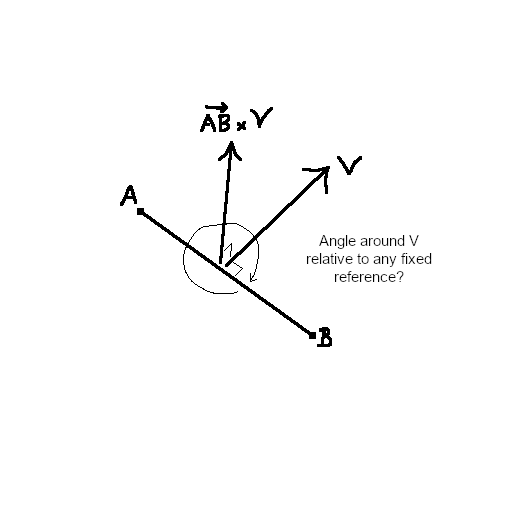
Bad drawing of the geometry

An alternative description of the geometry is that I have a cylinder with its long axis aligned with V, and the points A,B are opposite sides of the end-cap circumference... and I need to know the rotation of the cylinder around its long axis described by AB (relative to any arbitrary consistent 0 angle).

UPDATE: In case it breaks assumptions, my values are all measurements from a live camera, so the 'normal' vector V may not be exactly normal to AB... it should always be pretty close though (within a few degrees).

\$\endgroup\$
11
  • 1
    \$\begingroup\$ By construction, the angle between the vertical vector ABxV and AB as shown with the curved arrow in your diagram is always 90 degrees, or a numerical error away. Is there a different reference vector you wanted to measure the rotation of the whole system relative to? \$\endgroup\$
    – DMGregory
    Commented Mar 2, 2021 at 23:14
  • \$\begingroup\$ My bad, a poor diagram! Any arbitrary fixed reference will do - I don't know what would be suitable. The curve there was supposed to indicate the plane of rotation, not the actual reference axis. I'm using this to track a particular rotation (relative) so I don't really care what the 0 angle represents. \$\endgroup\$
    – PeteB
    Commented Mar 2, 2021 at 23:19
  • 1
    \$\begingroup\$ Try editing your question to elaborate on the application. You say this has something to do with a "live camera" - can you explain your vectors in terms of that application? That might give us a better intuition about what kinds of solutions are appropriate. \$\endgroup\$
    – DMGregory
    Commented Mar 2, 2021 at 23:20
  • 1
    \$\begingroup\$ Rotation has to be relative to an axis (in the cylinder example, it would be the center line), but with only 2 points, there are infinite possible orientations of the cylinder (and no clear reference... What would 7 mean as opposed to -3?). Center of rotation + arbitrary fixed vector (perhaps world "up"?) might be sufficient, or perhaps the centerline of the imaginary cylinder. It all depends on what you're trying to do \$\endgroup\$
    – Basic
    Commented Mar 2, 2021 at 23:50
  • 1
    \$\begingroup\$ I have two points and the cylinder vector. For a wrist we can say the vector passes through the mid-point of AB, so the cylinder is constrained in space except along its long axis. It can also rotate but only around the vector, and that is the measurement I need. World 'up' won't work because the vector could be pointing anywhere, including straight 'up'... so I think you've helped me clarify the question into two parts and I'll update it now! \$\endgroup\$
    – PeteB
    Commented Mar 3, 2021 at 0:32

1 Answer 1

1
\$\begingroup\$

The bad news is the Hairy Ball Theorem says there's no perfect way to do this.

Whenever we try to assign one standard reference direction to a particular plane, that will always be the same for any parallel plane (equivalently, for a given normal vector V), then our mapping must have a discontinuity somewhere. There will be a critical angle where, as we smoothly rotate our plane, the reference direction suddenly snaps to a point a different way, and our AB angle from the previous frame will no longer correspond to the angle from the new reference direction.

But for something that usually moves about gradually, you can carry your reference vector from the previous frame into the next one, something like this...

// Member variables.
private Vector3 _referenceUp = new Vector3(0, 1, 0);

// ...
// Then later, in Update or a similar method:

Vector3 right = Vector3.Cross(_referenceUp, V).normalized;
Vector3 up = Vector3.Cross(V, right).normalized;

float angle = Mathf.Atan2(Dot(AB, up), Dot(AB, right));

// Store for next frame's use.
_referenceUp = up

This avoids the Hairy Ball Theorem problem, by allowing us to pick more than one reference direction for a given plane, depending on the journey we took to get there. We enforce consistency over time, rather than consistency for a given input orientation.

If you want to keep _referenceUp somewhat aligned with world up when feasible, you can lerp it a small distance toward (0, 1, 0) after each frame.

\$\endgroup\$
3
  • \$\begingroup\$ Thanks! It looks like it was much harder problem than I gave it credit for. I've plugged in your suggestion and the numbers look reasonable - I'll set it as 'correct answer' as soon as I've verified it visually - I've got a weird variable range oscillation (I disabled the lerp and the wandering normal is moving quite smoothly, so I must have a bug elsewhere in my program). \$\endgroup\$
    – PeteB
    Commented Mar 3, 2021 at 4:40
  • \$\begingroup\$ Yep that works within limits - it's not great when the wrist goes vertical on the screen. I'm wondering if choosing a different reference might help that - for instance if it's the left arm it is unlikely to tilt far to the left (while still exposing the back of the hand) because the elbow/shoulder joint doesn't twist that way... so maybe using a reference vector (-1, 1, 0) might work better. \$\endgroup\$
    – PeteB
    Commented Mar 3, 2021 at 21:52
  • \$\begingroup\$ Yes, that has actually helped: Vector3 _referenceUp = new Vector3(-1, 1, 0).normalized; \$\endgroup\$
    – PeteB
    Commented Mar 3, 2021 at 22:25

You must log in to answer this question.

Not the answer you're looking for? Browse other questions tagged .