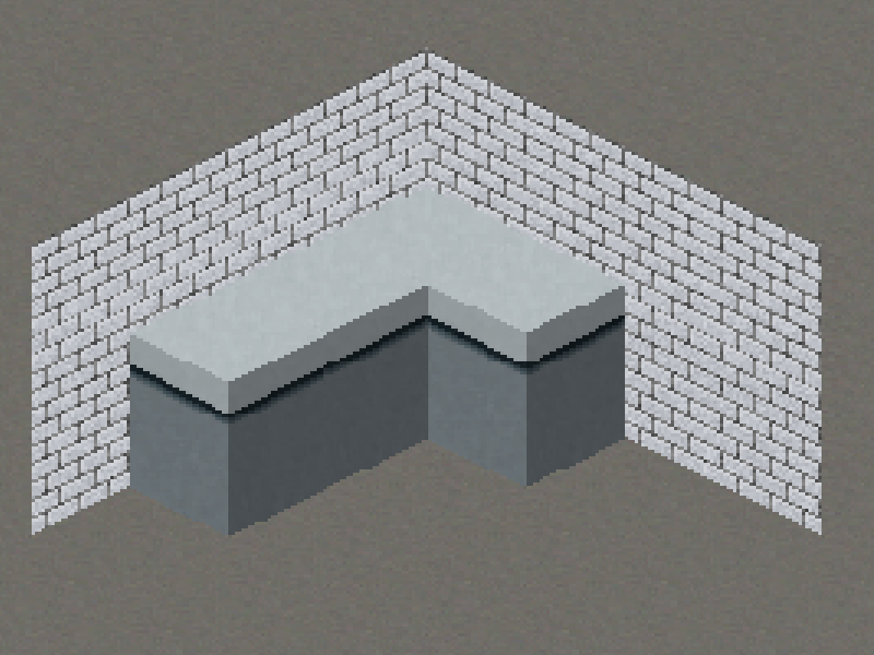
I am currently drawing a isometric world in 3D, meaning the floors and walls are all quads aligned to the original axis in the world and using a rotated orthogonal camera to "distort" the images into an isometric projection.
The textures of the walls and floors are just rectangular textures on a axis aligned quad, the camera is doing the rest. I am building a single mesh from everything and adding vertices in the order of back to front manually. So no OpenGL sorting is used. The order is important since I am using alpha blending.
The other quad represents an object on a tile but can very well be a dynamic object such as a player or NPC. This is currently drawn along the regular Y(up) axis. It's texture is already painted isometric and since there is an angle it gets distorted. To counteract this I am currently stretching the quad in Y(up) direction. This works fairly well but obviously it creates artifacts, especially when it needs tiling.
I figured my best option is to draw these as camera aligned billboard but I need control of the draw order, just like I am drawing it now so I can fit these objects in between walls and other objects. However I am not sure how to create these billboards properly. I could create a quad with the screen dimensions I need and then perhaps rotate the verts or perhaps change projection matrix when I need to draw a billboard. They obviously have to be aligned properly to the world.
So how would I approach this problem in detail? Perhaps with some code how to transform a quad to face the camera and keeping it aligned with the world? In particular, since I am using a fixed camera projection I would like to leverage this and reduce calculations if that is possible.
I have created the following method to translate vertices to have the quad face the camera. This "should" add a billboard in the center of my world but it does not.
public void addBillboardAtCenter(float x, float y, float z, FloorObject floorObject) {
    //Not sure if these are correct.
    Vector3 cameraRightWorldspace = new Vector3(1, 0, 0).mul(cam.invProjectionView);
    Vector3 cameraUpWorldspace = cam.up.cpy().mul(cam.invProjectionView);

    Vector3 bottomLeft = new Vector3(0, 0, 0); // center of billboard
    bottomLeft.add(cameraRightWorldspace.scl(-.5f));
    bottomLeft.add(cameraUpWorldspace.scl(-.5f));

    Vector3 topLeft = new Vector3(0, 0, 0); // center of billboard
    bottomLeft.add(cameraRightWorldspace.scl(-.5f));
    bottomLeft.add(cameraUpWorldspace.scl(.5f));

    Vector3 bottomRight = new Vector3(0, 0, 0); // center of billboard
    bottomLeft.add(cameraRightWorldspace.scl(.5f));
    bottomLeft.add(cameraUpWorldspace.scl(-.5f));

    Vector3 topRight = new Vector3(0, 0, 0); // center of billboard
    bottomLeft.add(cameraRightWorldspace.scl(.5f));
    bottomLeft.add(cameraUpWorldspace.scl(.5f));

    // Bottom left
    verts[vi++] = bottomLeft.x;
    verts[vi++] = bottomLeft.y;
    verts[vi++] = bottomLeft.z;
    verts[vi++] = floorObject.getU();
    verts[vi++] = floorObject.getV2();
    verts[vi++] = 1;

    // Bottom right halfway
    verts[vi++] = bottomRight.x;
    verts[vi++] = bottomRight.y;
    verts[vi++] = bottomRight.z;
    verts[vi++] = floorObject.getU2();
    verts[vi++] = floorObject.getV2();
    verts[vi++] = 1;

    // Top left
    verts[vi++] = topLeft.x;
    verts[vi++] = topLeft.y;
    verts[vi++] = topLeft.z;
    verts[vi++] = floorObject.getU();
    verts[vi++] = floorObject.getV();
    verts[vi++] = 1;

    // Top right halway
    verts[vi++] = topRight.x;
    verts[vi++] = topRight.y;
    verts[vi++] = topRight.z;
    verts[vi++] = floorObject.getU2();
    verts[vi++] = floorObject.getV();
    verts[vi++] = 1;
}
Another attempt, this yields a slightly rotated (27.5 degree?) version of my sprite with it's center positioned at the center of my world.
public void addBillboard(FloorObject floorObject) {
    Vector3 direction = new Vector3(-1, 0, 0).nor();
    Vector3 cameraDirection = cam.direction.cpy().nor();

    Vector3 leftRight = direction;

    float dot = cameraDirection.cpy().dot(direction);

    Vector3 updown = new Vector3(0, 1, 0);
    if (Math.abs(dot) < 1f) {
        updown = direction.cpy().crs(cameraDirection);
    }
    updown.nor();

    Vector3 position = new Vector3(0, 0, 0);

    Vector3 bottomLeft = position.cpy().add(updown).sub(leftRight);
    Vector3 topLeft = position.cpy().sub(updown).sub(leftRight);
    Vector3 bottomRight = position.cpy().add(updown).add(leftRight);
    Vector3 topRight = position.cpy().sub(updown).add(leftRight);

    // Bottom left
    verts[vi++] = bottomLeft.x;
    verts[vi++] = bottomLeft.y;
    verts[vi++] = bottomLeft.z;
    verts[vi++] = floorObject.getU();
    verts[vi++] = floorObject.getV2();
    verts[vi++] = 1;

    // Bottom right halfway
    verts[vi++] = bottomRight.x;
    verts[vi++] = bottomRight.y;
    verts[vi++] = bottomRight.z;
    verts[vi++] = floorObject.getU2();
    verts[vi++] = floorObject.getV2();
    verts[vi++] = 1;

    // Top left
    verts[vi++] = topLeft.x;
    verts[vi++] = topLeft.y;
    verts[vi++] = topLeft.z;
    verts[vi++] = floorObject.getU();
    verts[vi++] = floorObject.getV();
    verts[vi++] = 1;

    // Top right halway
    verts[vi++] = topRight.x;
    verts[vi++] = topRight.y;
    verts[vi++] = topRight.z;
    verts[vi++] = floorObject.getU2();
    verts[vi++] = floorObject.getV();
    verts[vi++] = 1;

}


