14
\$\begingroup\$

I know there are already a lot of resources about this, but I haven't found one that matches my coordinate system and I'm having massive trouble adjusting any of those solutions to my needs. What I learned is that the best way to do this is to use a transformation matrix. Implementing that is no problem, but I don't know in which way I have to transform the coordinate space.

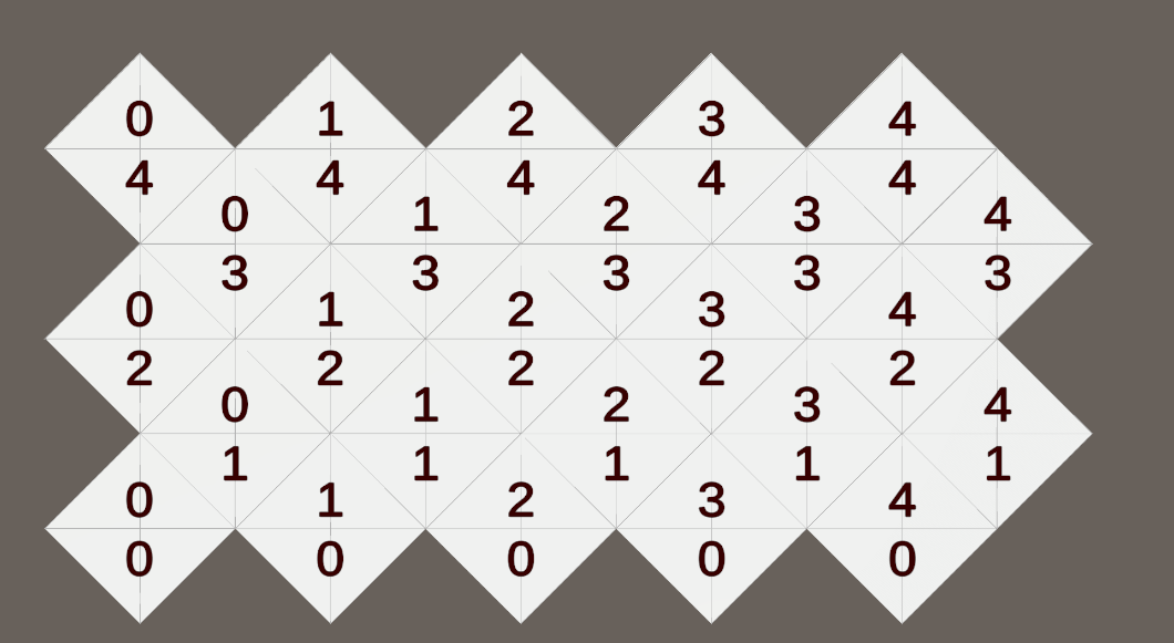
Here's an image that shows my coordinate system:

enter image description here

How do I transform a point on screen to this coordinate system?

\$\endgroup\$
3
  • \$\begingroup\$ Check this out: jsfiddle.net/Sd4ZP/18 \$\endgroup\$ Commented Dec 7, 2012 at 10:35
  • \$\begingroup\$ I can not see how this is helpful in any way. I think you didn't quite understand what I mean. \$\endgroup\$
    – Chris
    Commented Dec 7, 2012 at 14:57
  • \$\begingroup\$ It does the transformation, just the other way around, so you need to reverse it. \$\endgroup\$ Commented Dec 8, 2012 at 15:07

5 Answers 5

26
\$\begingroup\$

First, here is the code. An explanation will follow:

/*
 * tw, th contain the tile width and height.
 *
 * hitTest contains a single channel taken from a tile-shaped hit-test
 * image. Data was extracted with getImageData()
 */

worldToTilePos = function(x, y) {

    var eventilex = Math.floor(x%tw);
    var eventiley = Math.floor(y%th);

    if (hitTest[eventilex + eventiley * tw] !== 255) {
        /* On even tile */

        return {
            x: Math.floor((x + tw) / tw) - 1,
            y: 2 * (Math.floor((y + th) / th) - 1)
        };
    } else {
        /* On odd tile */

        return {
            x: Math.floor((x + tw / 2) / tw) - 1,
            y: 2 * (Math.floor((y + th / 2) / th)) - 1
        };
    }
};

Note that this code won't work out of the box for the map shown in your question. This is because you have the odd tiles offset to the left, whereas the odd tile is more usually offset to the right (As is the case in the tiled map editor). You should be able to easy remedy this by tweaking the x value returned in the odd-tile case.

Explanation

This may seem to be a slightly more brute-force method of accomplishing this task, but it does at least have the advantage of being pixel perfect and slightly more flexible.

The trick is in viewing the map not as a single staggered grid, but as two grids overlayed on top of one another. There's the odd-rows grid and the even-rows grid, but let's call them red and green instead so that we can create a pretty diagram...

Two grids, red and green

Notice on the right of that image I've marked a point with a purple dot. This is the example point we'll try to find in our original tile-space.

The thing to notice about any point in the world is that it will always lie in exactly two regions - a red one and a green one (Unless it's on an edge, but you'll likely be clipping within the jagged edge boundary anyway). Let's find those regions...
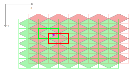
Two candidate regions

Now to pick which of the two regions is the correct one. There will always be exactly one answer.

From here we could do some more simple arithmetic and work out the squared distance from our sample point to each centre point of the two regions. Whichever is the closest will be our answer.

There is an alternative way however. For each test region, we sample a bitmap that matches the exact shape of our tiles. We sample it at a point translated into local coordinates for that single-tile. For our example it would look something like this:
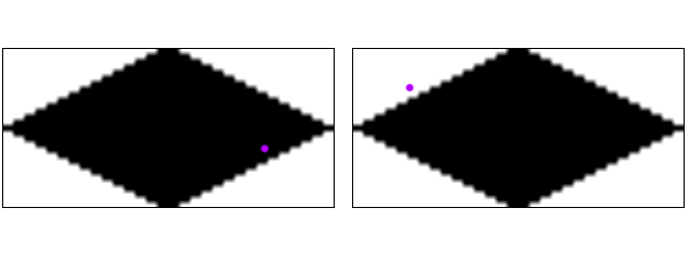
Point samples

One the left we check the green region and get a hit (Black pixel). On the right we test the red region and get a miss (White pixel). The second test is of course redundant since it will always be exactly one or the other, never both.

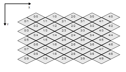
We then arrive at the conclusion that we have a hit in the odd tile at 1,1. This coordinate should be simple to map to the original tile coordinates using a different transformation for odd and even rows.

This method also allows you to have simple per-pixel properties on the pixel test bitmap(s). E.g. white is off-tile, black is a hit, blue is water, red is solid.
\$\endgroup\$
0
1
\$\begingroup\$

I think the problem you're having is with your coordinate space. The coordinates you've given the tiles are not really an isometric projection - You need to think of the xAxis as going diagonal down-right and the yAxis as going diagonal down-left (or some variant of that)

right now if you move along the illustrated coordinate axes you'll be traveling in a diagonal direction in "tile space" so the squares end up as diamonds (and everything will be more complex)

The transformation matrix you're looking for is one built out of those x and y axes. It is effectively the same as doing the following calculation.

screenOffsetXY = screenPointXY - tileOriginXY;
tileX = dot(screenOffsetXY, xAxis) / tileWidth;
tileY = dot(screenOffsetXY, yAxis) / tileWidth;

Edit: I just came across a similar question (but with the coordinate system I was talking about) and someone gave a much more thorough answer here:

How to convert mouse coordinates to isometric indexes?

\$\endgroup\$
0
\$\begingroup\$

Basically you want to get the position of the mouse in the window using an event listener, you need to remove the offset of the canvas position in the window from the mouse positions, so the mouse position is then relative to the canvas.

function mouseTwoGridPosition(e){

var mousex = e.pageX; //mouse position x
var mouseY = e.pageY;  //mouse position y
var canvas_width = 1000; //pixels
var offset_left = 100; //offset of canvas to window in pixels
var offset_top = 150; //offset of canvas to window in pixels

var isotile = 64; //if iso tile is 64 by 64

//get mouse position relative to canvas rather than window
var x = mousex - canvas_width/2 - offset_left;
var y = mousey - offset_top;


//convert to isometric grid
var tx = Math.round( (x + y * 2) / isotile) - 1;
var ty = Math.round((y * 2 - x) / isotile) - 1;

 //because your grid starts at 0/0 not 1/1 we subtract 1 
 // this is optional based on what grid number you want to start at


   return [tx,ty];
}

I will assume you know how to do event listening on canvas' for mousemove, otherwise you might want to learn more JS before you consider isometric game design :D

\$\endgroup\$
6
  • \$\begingroup\$ Isn't this a bit too simple? I want it to match the form of the iso tile perfectly. You are just checking a rectangular area if I understand this correctly. \$\endgroup\$
    – Chris
    Commented Dec 7, 2012 at 0:51
  • \$\begingroup\$ what do you mean by "form" of the isotile... for example say your mouse is within the diamond shaped bounds of 0:1 the return will be 0:1 until your mouse leaves that boundary. If your tiles vary in size - then my method will not work. The function provided is what i use and it works fine for me. \$\endgroup\$
    – Dave
    Commented Dec 7, 2012 at 0:52
  • \$\begingroup\$ Just wondering, because all the other solutions are way more complicated. Tiles are the same size of course so I will check this out. \$\endgroup\$
    – Chris
    Commented Dec 7, 2012 at 0:53
  • \$\begingroup\$ Well tinker with it make sure you get the correct offset of canvas left and top - and canvas width, when you do the maths will work fine (also the isotile size width). \$\endgroup\$
    – Dave
    Commented Dec 7, 2012 at 0:55
  • \$\begingroup\$ Are you sure you are using the same coordinate system as me? It's still completely off. \$\endgroup\$
    – Chris
    Commented Dec 7, 2012 at 1:25
0
\$\begingroup\$

I solved this by changing the coordinate space. It now starts without a offset in the first row and for that I found a working example which I was able to adjust a bit.

    hWidth = this.tileset.tileSize.width / 2;
    hHeight = this.tileset.tileSize.height / 2;

    pX = point.x - halfWidth;
    pY = point.y - halfHeight;

    x = Math.floor((pX + (pY - hHeight) * 2) / this.tileset.tileSize.width);
    y = Math.floor((pY - (pX - hWidth) * 0.5) / this.tileset.tileSize.height);

    tx = Math.floor((x - y) / 2) + 1 + this.camera.x;
    ty = y + x + 2 + this.camera.y;
\$\endgroup\$
0
\$\begingroup\$

I've implemented an alternative method for detecting grid positions in an isometric Unity game without using a hitmap. Instead, I'm using a combination of mesh colliders and raycasting. Here's my implementation:

// ... other fields and methods ...

public bool IsOddRowAtPoint(Vector3 point)
{
    Ray ray = new Ray(point + Vector3.up * 10, Vector3.down);
    RaycastHit hit;
    if (meshCollider.Raycast(ray, out hit, 20f))
    {
        int triangleIndex = hit.triangleIndex * 3;
        int vertexIndex = triangles[triangleIndex];
        return isOddRow[vertexIndex];
    }
    return false; // Default value if no hit is detected
}

// ... method to create mesh and set up isOddRow list ...


// ... other fields and methods ...

void TouchCell(Vector3 position)
{
    position = transform.InverseTransformPoint(position);
    bool isOddRow = isoMesh.IsOddRowAtPoint(position);
    IsoCoordinates coordinates = IsoCoordinates.FromPosition(position, isOddRow);
    
    Debug.Log($"Touched at {coordinates.ToString()}, Is Odd Row: {isOddRow}");
}

public static IsoCoordinates FromPosition(Vector3 position, bool isOddRow)
{
    float x = position.x / IsoMetrics.cellWidth;
    float z = position.z / (IsoMetrics.cellHeight);
    int iZ = 0;
    if (isOddRow)
    {
        x -= 0.5f;
        z += 0.5f;
        iZ = Mathf.FloorToInt((z)) * 2 - 1;
    }
    else
    {
        iZ = Mathf.FloorToInt((z)) * 2;
    }
    int iX = Mathf.FloorToInt(x);
    return new IsoCoordinates(iX, iZ);
}

This approach uses a mesh collider and stores whether each triangle in the mesh belongs to an odd or even row. When detecting a grid position, it raycasts against the mesh and checks the isOddRow status of the hit triangle.

What I'm unsure of given my method

How does this method compare performance-wise to using a hitmap?

Are there any potential issues or edge cases I should be aware of?

Is there a more efficient way to store and retrieve the odd/even row information for each cell?

How well would this scale for larger grids?

My Grid Currently after following this awesome tutorial https://catlikecoding.com/unity/tutorials/hex-map/part-1/

My Grid

Tags: [unity3d] [isometric] [grid] [game-development] [c#]

\$\endgroup\$
2
  • \$\begingroup\$ If you're looking to answers to the questions you asked, you should post this as a new Question thread, rather than as an answer to an existing question. The StackExchange framework doesn't allow users to post answers replying to other answers. \$\endgroup\$
    – DMGregory
    Commented Jul 7 at 3:17
  • \$\begingroup\$ Thank you for informing me, @DMGregory. I appreciate the guidance. I just wanted to get across the issues and unsure aspects of my method, will make it more clear next time and I'll post a question thread for this if needed, when i explore these questions in my project later. \$\endgroup\$
    – Mark Ford
    Commented Jul 8 at 22:52

You must log in to answer this question.

Not the answer you're looking for? Browse other questions tagged .