9
\$\begingroup\$

I've been trying to understand voxel rendering and have been looking at dual contouring (DC).

So far I understand this much:

  1. Run a density function for a set of grid points (i.e noise function)
  2. Find which edges in the gird contain changes between end-points
  3. From these edges create intersection points (i.e vectors)

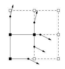
Now this is where I'm stuck, next would be to generate normals, but how? When looking at this topic this image normally crops up.

                                                   A signed grid with edges tagged by Hermite data

Doing research indicates that the normals would be generated from an isosurface. Is it correct to think that I go from noise to isosurface to normals? If so how would I accomplish each step?

To my understanding, the next step would be the following from the DC paper;

For each edge that exhibits a sign change, generate a quad connecting the minimizing vertices of the four cubes containing the edge.

Is this quote represented by the above image?

Finally the next step would be to run the QEF with the intersecting points and normals and this would generate my vertex data. Is this correct?

\$\endgroup\$
1
  • \$\begingroup\$ As i understand this process it's something like ... noise > point cloud > iso surface > normals ... but i'm not smart enough to claim I can explain this process properly so i'm not going to attempt an answer. \$\endgroup\$
    – War
    Commented Sep 17, 2014 at 14:31

2 Answers 2

4
\$\begingroup\$

The normals would be generated based on the gradient of the density function at the same time that you get the intersection points between the edges and the surface. If it's something simple and closed-form like a sphere then you can calculate the normals analytically, but with noise you'll need to take samples.

You have the next steps in the wrong order. First, you generate a vertex for each cell that exhibits a sign change. The QEF you are minimizing is simply the total distance to each of the planes that are defined by the intersection point/normal pairs for that cell. Then you walk through the edges that exhibit sign changes and create a quad using the four adjacent vertices (which are guaranteed to have been generated in the last step).

Now, my biggest hurdle in implementing this was solving the QEF. I actually came up with a simple iterative solution that will run well on (for example) a GPU in parallel. Basically, you start the vertex in the centre of the cell. Then you average all the vectors taken from the vertex to each plane and move the vertex along that resultant, and repeat this step a fixed number of times. I found moving it ~70% along the resultant would stabilize in the least amount of iterations.

\$\endgroup\$
8
  • \$\begingroup\$ So lets say I have a cell/voxel that I know exhibits a sign change (i.e a case like MC), I have ran a noise function for each 8 corners of the cell to find its density. What I'm having trouble understanding is from this how do I find the variables x, n and p of the the QEF? \$\endgroup\$
    – Soapy
    Commented Sep 22, 2014 at 11:47
  • \$\begingroup\$ x is the vertex position. For each intersection point you have p (the position) and n (the normal), which make up the planes that I was talking about. \$\endgroup\$
    – jmegaffin
    Commented Sep 22, 2014 at 14:43
  • \$\begingroup\$ p is found by finding where the weighted average of the two densities along the edge is zero. Then you calculate n by taking the gradient of your density function at p. \$\endgroup\$
    – jmegaffin
    Commented Sep 22, 2014 at 14:50
  • \$\begingroup\$ So basically for each cube I calculate the p and n for each 12 edges, and then run the QEF for each cell edges p and n into x, which in your example is at the centre of a voxel/cell to start with? Then if four cells share the same edge, I create a quad connecting each four cells x? And is the resultant quad my polygonal data? \$\endgroup\$
    – Soapy
    Commented Sep 22, 2014 at 17:12
  • \$\begingroup\$ Not every edge is going to have an intersection, so you aren't necessarily solving the QEF for 12 planes. Other than that you've got it! \$\endgroup\$
    – jmegaffin
    Commented Sep 22, 2014 at 17:47
1
\$\begingroup\$

From reading the paper up to page 2, it appears the weights of volume are stored at the corners of the grid instead of being the weight of the cube itself as normal Marching Cubes style algorithms prefer. These corner weights define a point between along the edge between 2 corners where there is a sign change from corner to corner.. Edges with sign changes also store a normal for the edge which are the angled line in your 2D representation in the OP. That normal information is defined during the creation of the volume (by whatever editing tool or procedural volume creation method is being used), not after the isosurface is generated as would be expected by a Marching Cubes style algorithm. This normal data "states" that the line/surface passing through the point must have the predefined normal value. In cases where Marching Cubes would bend the line at that point to mate up with another point on an adjacent edge, Extended Marching Cubes and Dual Contouring both extend the line/surface out until it intersects with the line/surface passing through the point on the adjacent edge that has a different normal value. This allows creating sharp corners from the volume data where basic Marching Cubes algorithms would round off the surface somewhat. I'm not quite understanding how QEFs (quadratic error functions) play into this except that it seems they make it easier to compute the extended point within a cube where a corner will be located.

Note that I've been talking about lines and edges here in the 2D sense as depicted by the representation in the OP.. I would have to do some more reading and thinking to extend this to 3D for volumetric mesh generation.

To address the 2nd half of your question about how to generate the normals, and thinking from a noise driven procedural point of view, it seems like you would fill your volume with noise data then look for edges with sign changes, then examine the 4 cubes that share the edge to figure out where what triangles are going to be generated, and compute the vertex normal like you would for any other intersection of multiple triangles, taking the average of the normals for each triangle that shares the vertex. This is very speculative on my part as the paper deals mostly with CSG operations and volumes generated from scan-converted meshes, both of which have well defined normals on the surfaces.

I hope at least the 1st part of this answer addresses the differences in how the weight data is represented and used in a manner quite different from basic Marching Cubes, and why the normal data has to be created fairly early on in the volume generation process, where with basic marching cubes normals are typically created as a last stage in the mesh generation process.
\$\endgroup\$

You must log in to answer this question.

Not the answer you're looking for? Browse other questions tagged .