12
\$\begingroup\$

I’ve created an algorithm which converts any curve i.e. path into minimum number of points so that I can save it into a file or database.

The method is simple: it moves three points in equal steps and measures the angle between the lines these points form. If the angle is bigger than the tolerance then it creates a new cubic curve to that point. Then it moves the lines forward and measures the angle again…

For those who know Android Path Class - Note that the dstPath is a custom class, which records the points into an Array so I can save the points later, while the srcPath is the result of a Regions union and therefore has no key points for me to save.

The problem is that the circle does not look smooth as you can see in this image, produced by the code below, where the source path consists of a perfect circle and rectangle. I tried to change angle of tolerance and the steps length, but nothing helps. I wonder if you can suggest any improvement to this algorithm, or a different approach.

EDIT: I have now posted the entire code for those who use Android java, so they can easily try and experiment.
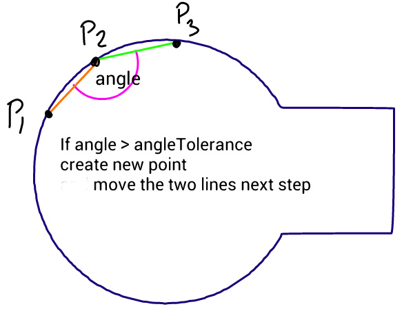
enter image description here

public class CurveSavePointsActivity extends Activity{

    public void onCreate(Bundle savedInstanceState) {
        super.onCreate(savedInstanceState);

        setContentView(new CurveView(this));
    }

    class CurveView extends View{

        Path srcPath, dstPath;
        Paint srcPaint = new Paint(Paint.ANTI_ALIAS_FLAG);
        Paint dstPaint = new Paint(Paint.ANTI_ALIAS_FLAG);

        public CurveView(Context context) {
            super(context);

            srcPaint.setColor(Color.BLACK);
            srcPaint.setStyle(Style.STROKE);
            srcPaint.setStrokeWidth(2);
            srcPaint.setTextSize(20);

            dstPaint.setColor(Color.BLUE);
            dstPaint.setStyle(Style.STROKE);
            dstPaint.setStrokeWidth(2);
            dstPaint.setTextSize(20);

            srcPath = new Path();
            dstPath = new Path();

        }

        @Override
        protected void onSizeChanged(int w, int h, int oldw, int oldh) {
            super.onSizeChanged(w, h, oldw, oldh);

            //make a circle path
            srcPath.addCircle(w/4, h/2, w/6 - 30, Direction.CW);

            //make a rectangle path
            Path rectPath = new Path();
            rectPath.addRect(new RectF(w/4, h/2 - w/16, w*0.5f, h/2 + w/16), Direction.CW);


            //create a path union of circle and rectangle paths
            RectF bounds = new RectF();
            srcPath.computeBounds(bounds, true);
            Region destReg = new Region();
            Region clip = new Region();
            clip.set(new Rect(0,0, w, h));
            destReg.setPath(srcPath, clip);
            Region srcReg = new Region();
            srcReg.setPath(rectPath, clip); 
            Region resultReg = new Region();
            resultReg.op(destReg, srcReg, Region.Op.UNION);
            if(!resultReg.isEmpty()){
                srcPath.reset();
                srcPath.addPath(resultReg.getBoundaryPath());
            }

            //extract a new path from the region boundary path
            extractOutlinePath();

            //shift the resulting path bottom left, so they can be compared
            Matrix matrix = new Matrix();
            matrix.postTranslate(10, 30);
            dstPath.transform(matrix);

        }

         @Override 
            public void onDraw(Canvas canvas) { 
                super.onDraw(canvas);    
                canvas.drawColor(Color.WHITE);
                canvas.drawPath(srcPath, srcPaint);
                canvas.drawPath(dstPath, dstPaint);

                canvas.drawText("Source path", 40, 50, srcPaint);
                canvas.drawText("Destination path", 40, 100, dstPaint);
         }


         public void extractOutlinePath() {

             PathMeasure pm = new PathMeasure(srcPath, false); //get access to curve points

             float p0[] = {0f, 0f}; //current position of the new polygon
             float p1[] = {0f, 0f}; //beginning of the first line
             float p2[] = {0f, 0f}; //end of the first & the beginning of the second line
             float p3[] = {0f, 0f}; //end of the second line

             float pxStep = 5; //sampling step for extracting points
             float pxPlace  = 0; //current place on the curve for taking x,y coordinates
             float angleT = 5; //angle of tolerance

             double a1 = 0; //angle of the first line
             double a2 = 0; //angle of the second line

             pm.getPosTan(0, p0, null); //get the beginning x,y of the original curve into p0
             dstPath.moveTo(p0[0], p0[1]); //start new path from the beginning of the curve
             p1 = p0.clone(); //set start of the first line

             pm.getPosTan(pxStep, p2, null); //set end of the first line & the beginning of the second

             pxPlace = pxStep * 2;
             pm.getPosTan(pxPlace, p3, null); //set end of the second line


             while(pxPlace < pm.getLength()){
             a1 = 180 - Math.toDegrees(Math.atan2(p1[1] - p2[1], p1[0] - p2[0])); //angle of the first line
             a2 = 180 - Math.toDegrees(Math.atan2(p2[1] - p3[1], p2[0] - p3[0])); //angle of the second line

             //check the angle between the lines
             if (Math.abs(a1-a2) > angleT){

               //draw a straight line to the first point if the current p0 is not already there
               if(p0[0] != p1[0] && p0[1] != p1[1]) dstPath.quadTo((p0[0] + p1[0])/2, (p0[1] + p1[1])/2, p1[0], p1[1]);

               dstPath.quadTo(p2[0] , p2[1], p3[0], p3[1]); //create a curve to the third point through the second

               //shift the three points by two steps forward
               p0 = p3.clone();
               p1 = p3.clone();
               pxPlace += pxStep;
               pm.getPosTan(pxPlace, p2, null); 
               pxPlace += pxStep;
               pm.getPosTan(pxPlace, p3, null);
               if (pxPlace > pm.getLength()) break;
             }else{
               //shift three points by one step towards the end of the curve
               p1 = p2.clone(); 
               p2 = p3.clone();
               pxPlace += pxStep;
               pm.getPosTan(pxPlace, p3, null); 
             }
             }
             dstPath.close();
         }
    }

}

Here's a comparison between the original and what my algorithm produces:
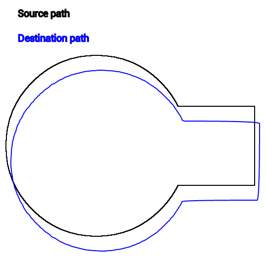
comparison between paths; noticeably smoother corners on the derivative

\$\endgroup\$
9
  • \$\begingroup\$ why not use b-splines? \$\endgroup\$ Commented Feb 12, 2013 at 23:20
  • 4
    \$\begingroup\$ if you know the thing is a circle and a rectangle, why not store a circle and a rectangle? And in generalized form - whatever input generated your thing is probably a reasonable format to store it in. If you are looking for a compression scheme that seems like a different question (or at least we'd need a lot more info about the source data to be helpful). \$\endgroup\$
    – Jeff Gates
    Commented Feb 13, 2013 at 11:43
  • \$\begingroup\$ It can be any unpredicatable shape as I said in the first sentence - the circle and rectange here are only a test example. \$\endgroup\$
    – Lumis
    Commented Feb 13, 2013 at 12:44
  • \$\begingroup\$ @Lumis you really should look into b-splines, it what they're for. Any reason to try implement your own solution? \$\endgroup\$ Commented Feb 13, 2013 at 18:07
  • 1
    \$\begingroup\$ Well path class will construct those curves with splines so you're already using it. I have another suggestion,less math oriented: instead of saving points, save the user input (command pattern) and replay it to build the same "image". \$\endgroup\$ Commented Feb 13, 2013 at 22:51

8 Answers 8

6
+300
\$\begingroup\$

I think you have two problems:

Non-symmetric control points

Initially you start with equal distances between p0 to p1 and p1 to p2. If the tolerance angle between the line segments is not met, you move p1 and p2 forward, but keep p0 where it was. This increases the distance between p0 to p1 while keeping the distance between p1 to p2 the same. When you create a curve using p1 as the control points, it can be heavily biased towards p2 depending on how many iterations have passed since the last curve. If you would move p2 twice the amount than p1, you would get even distances between the points.

Quadratic curves

As mentioned in other answers as well, quadratic curve is not very good for this case. Adjacent curves you create should share a control point and a tangent. When your input data is just points, Catmull-Rom Spline is a good choice for that purpose. It's a cubic Hermite curve, where the tangents for the control points are calculated from previous and next points.

The Path API in Android supports Bézier curves, which are a little different than Hermite curves regarding parameters. Fortunately Hermite curves can be converted to Bézier curves. Here is the first example code I found when Googling. This Stackoverflow answer also seems to give the formula.

You also mentioned the problem of sharp edges. With the input data you have, it's impossible to detect if there is an actual sharp corner or just a very steep curve. If this becomes a problem, you can make the iteration more adaptive by increasing / decreasing the step on-the-fly as needed.

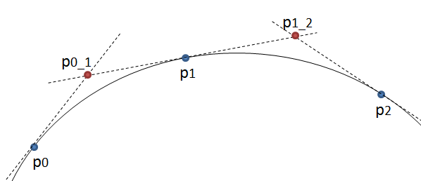
Edit: After further thinking quadratic curves could be used after all. Instead of drawing a quadratic curve from p0 to p2 using p1 as the control point, draw it from p0 to p1 using a new point p0_1 as the control points. See the picture below. New control points

If p0_1 is in the intersection of the tangents in p0 and p1, the result should be smooth. Even better, since PathMeasure.getPosTan() returns also tangent as the third parameter, you can use actual accurate tangents instead of approximations from adjacent points. With this approach you need less changes to your existing solution.

Based on this answer, the intersection point can be calculated with the following formula:

getPosTan(pxPlace0, p0, t0); // Also get the tangent
getPosTan(pxPlace1, p1, t1);
t1 = -t1; // Reverse direction of second tangent
vec2 d = p1 - p0;
float det = t1.x * t0.y - t1.y * t0.x;
float u = (d.y * t1.x - d.x * t1.y) / det;
float v = (d.y * t0.x - d.x * t0.y) / det; // Not needed ... yet
p0_1 = p0 + u * t0;

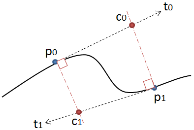
This solution however works only if both u and v are non-negative. See the second picture: Rays don't intersect

Here the rays don't intersect although the lines would, since u is negative. In this case it's not possible to draw a quadratic curve that would smoothly connect to the previous one. Here you need the bézier curves. You can calculate the control points for it either with the method given earlier in this answer or derive them directly from the tangents. Projecting p0 to the tangent ray p0+u*t0 and vise versa for the other ray gives both of the control points c0 and c1. You can also adjust the curve by using any point between p0 and c0 instead of c0 as long as it lies on the tangent ray.

Edit2: If your drawing position is in p1, you can calculate the bezier control points to p2 with the following pseudo code:

vec2 p0, p1, p2, p3; // These are calculated with PathMeasure
vec2 cp1 = p1 + (p2 - p0) / 6;
vec2 cp2 = p2 - (p3 - p1) / 6;

With these you can append a path from p1 to p2:

path.cubicTo(cp1.x, cp1.y, cp2.x, cp2.y, p2.x, p2.y);

Replace the vector operations with per component operations on float[2] arrays to match your code. You start by initializing p1 = start; and p2 and p3 are the next points. p0 is initially undefined. For the first segment where you don't have p0 yet, you can use a quadratic curve from p1 to p2 with cp2 as the control point. The same for the end of the path where you don't have p3, you can draw a quadratic curve from p1 to p2 with cp1 as the control point. Alternatively you can initialize p0=p1 for the first segment and p3=p2 for the last segment. After every segment you shift the values p0 = p1; p1 = p2; and p2 = p3; when moving forward.

When you are saving the path, you just save all points p0 ... pN. No need to save the control points cp1 and cp2, as they can be calculated as needed.

Edit3: As it seems to be hard to get good input values for the curve generation, I propose another approach: Use serialization. Android Path doesn't seem to support it, but fortunately Region class does. See this answer for the code. This should give you the exact result. It might take some space in the serialized form if it's not optimized, but in that case it should compress very well. Compression is easy in Android Java using GZIPOutputStream.

\$\endgroup\$
13
  • \$\begingroup\$ That sounds promising. However it is not p0 but p1,p2,p3 that are used, p0 is only for storing new definite points when they are calculated and for the sake of straight lines, so that they are not sampled each step. Can you help me how to calculate x,y for new control points? \$\endgroup\$
    – Lumis
    Commented Mar 7, 2013 at 21:25
  • \$\begingroup\$ I could do that later, but meanwhile check out stackoverflow.com/questions/2931573/…. With u and v you can get the intersection point. \$\endgroup\$
    – msell
    Commented Mar 7, 2013 at 21:49
  • \$\begingroup\$ Thank you for the help, I would like to try this, but it needs to be writen in Java for Android. There is no vector2 and t1 and p1 etc are float arrays so I cannot do any direct operation on them like t1 = -t1, or u*t0. I assume that t1 = -t1 means t1.x = -t1x; t1.y = -t1.y etc, right? \$\endgroup\$
    – Lumis
    Commented Mar 8, 2013 at 9:41
  • \$\begingroup\$ Yes, that was just pseudo code to make it more compact and readable. \$\endgroup\$
    – msell
    Commented Mar 8, 2013 at 9:52
  • \$\begingroup\$ Well, the plot is thickening. Because the region intersection of two paths in Android returns a path which is NOT anti-aliased, the tangents are over the place. So the proper solution would be to drive some smooth curve through the given points first and then sample it. Your code works perfectly fine on an anti-aliased path, it produces proper control points. \$\endgroup\$
    – Lumis
    Commented Mar 8, 2013 at 10:29
13
\$\begingroup\$

What would the W3C do?

The internet has had this problem. The World Wide Web Consortium noticed. It has a recommended standard solution since 1999: Scalable Vector Graphics (SVG). It's an XML-based file format specifically designed for storing 2D shapes.

"Scalable-what?"

Scalable Vector Graphics!

  • Scalable: It's meant to scale smoothly to any size.
  • Vector: It's based on the mathematical notion of vectors.
  • Graphics. It's meant to make pictures.

Here's the technical specification for SVG version 1.1.
(Don't be scared by the name; It's actually pleasant to read.)

They've written down exactly how basic shapes like circles or rectangles are to be stored. For example, rectangles have these properties: x, y, width, height, rx, ry. (The rx and ry can be used for rounded corners.)

Here's their example rectangle in SVG: (Well, two really -- one for the canvas outline.)

<?xml version="1.0" standalone="no"?>
<!DOCTYPE svg PUBLIC "-//W3C//DTD SVG 1.1//EN" 
  "http://www.w3.org/Graphics/SVG/1.1/DTD/svg11.dtd">
<svg width="12cm" height="4cm" viewBox="0 0 1200 400"
     xmlns="http://www.w3.org/2000/svg" version="1.1">
  <desc>Example rect01 - rectangle with sharp corners</desc>

  <!-- Show outline of canvas using 'rect' element -->
  <rect x="1" y="1" width="1198" height="398"
        fill="none" stroke="blue" stroke-width="2"/>

  <rect x="400" y="100" width="400" height="200"
        fill="yellow" stroke="navy" stroke-width="10"  />
</svg>

Here's what it represents:

a yellow rectangle with a blue outline

As the specification says, you're free to leave out some of the properties if you don't need them. (For example, rx and ry attributes weren't used here.) Yes, there's a ton of cruft at the top about DOCTYPE which you won't need just for your game. They're are optional too.

Paths

SVG paths are "paths" in the sense that if you put a pencil to a paper, move it around and eventually raise it again, you have a path. They don't have to be closed, but they might be.

Each path has a d attribute (I like to think it stands for "draw"), containing path data, a sequence of commands for basically just putting a pen to a paper and moving it around.

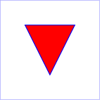
They give the example of a triangle:

<?xml version="1.0" standalone="no"?>
<!DOCTYPE svg PUBLIC "-//W3C//DTD SVG 1.1//EN" 
  "http://www.w3.org/Graphics/SVG/1.1/DTD/svg11.dtd">
<svg width="4cm" height="4cm" viewBox="0 0 400 400"
     xmlns="http://www.w3.org/2000/svg" version="1.1">
  <title>Example triangle01- simple example of a 'path'</title>
  <desc>A path that draws a triangle</desc>
  <rect x="1" y="1" width="398" height="398"
        fill="none" stroke="blue" />
  <path d="M 100 100 L 300 100 L 200 300 z"
        fill="red" stroke="blue" stroke-width="3" />
</svg>

a red triangle

See the d attribute in the path?

d="M 100 100 L 300 100 L 200 300 z"

The M is a command for Move to (followed by coordinates), the Ls are for Line to (with coordinates) and z is a command to close the path (i.e. draw a line back to the first location; that doesn't need coordinates).

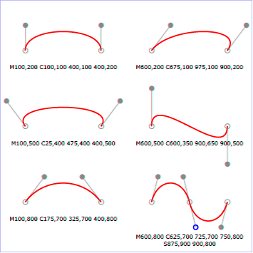
Straight lines are boring? Use the cubic or quadratic Bézier commands!

some cubic Béziers

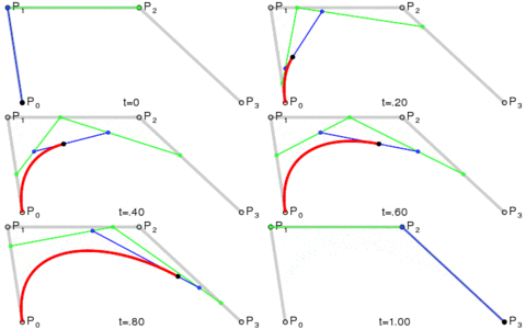
The theory behind Bézier curves is covered well elsewhere (such as on Wikipedia), but here's the executive summary: Béziers have a start and end point, with possibly many control points that influence where the curve in between is going.

tracing a quadratic Bézier

The specification also gives instructions for converting most basic shapes into paths in case you want to.

Why and when to use SVG

Decide carefully if you want to go down this path (pun intended), because it's really quite complicated to represent any arbitrary 2D shape in text! You can make your life so much easier if you e.g. limit yourself to just paths made of (potentially really many) straight lines.

But if you do decide you want arbitrary shapes, SVG is the way to go: It has great tool support: You can find many libraries for XML parsing at the low level and SVG editor tools at the high level.

Regardless, the SVG standard sets a good example.

\$\endgroup\$
2
  • \$\begingroup\$ The question is about converting a curve into points, not saving it. But thank you for this reference, it is good to know about SVG standard. \$\endgroup\$
    – Lumis
    Commented Mar 10, 2013 at 2:09
  • \$\begingroup\$ @Lumis The title and content would suggest otherwise. Consider rephrasing the question. (Or, now that this one is quite established, asking another one.) \$\endgroup\$
    – Anko
    Commented Mar 10, 2013 at 11:53
4
\$\begingroup\$

Your code contains a misleading comment:

dstPath.quadTo(p2[0] , p2[1], p3[0], p3[1]); //create a curve to the third point through the second

A quadratic bezier curve does not go through the second point. If you want to go through the second point you need a different type of curve, such as a hermite curve. You may be able to convert the hermite curves into beziers so that you can use the Path class.

Another suggestion is instead of sampling the points, use the mean of the points you're skipping over.

Another suggestion is instead of using an angle as a threshold, use the difference between the actual curve and the approximate curve. Angles aren't the real problem; the real problem is when the set of points doesn't fit a bezier curve.

Another suggestion is to use cubic beziers, with the tangent of one matching the tangent of the next. Otherwise (with quadratics) I think your curves won't match up smoothly.

\$\endgroup\$
1
  • \$\begingroup\$ You are right, the second point only "pulls" the curve towards it. The cubicTo requires two control points instead of one as the quadTo. The problem is of course how to get right control points. Note that I don't want to lose sharp corners as the source Path can be a combination of any shape straight or round - basically I am making an image selection tool where I can save the selected path. \$\endgroup\$
    – Lumis
    Commented Feb 15, 2013 at 11:53
4
\$\begingroup\$

To get a smoother intersection of two paths, you could scale them up before intersection and scale them down after.

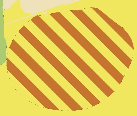
I don't know if it's a good solution, but it worked well for me. It's also fast. In my example, I intersect a rounded path with a pattern I created (stripes). It looks good even when scaled.

Here my code:

    Path mypath=new Path(<desiredpath to fill with a pattern>);
    String sPatternType=cpath.getsPattern();

    Path pathtempforbounds=new Path(cpath.getPath());
    RectF rectF = new RectF();
     if (sPatternType.equals("1")){
         turnPath(pathtempforbounds, -45);
     }
     pathtempforbounds.computeBounds(rectF, true);

     float ftop=rectF.top;
     float fbottom=rectF.bottom;
     float fleft=rectF.left;
     float fright=rectF.right;
     float xlength=fright-fleft;

     Path pathpattern=new Path();

     float ypos=ftop;
     float xpos=fleft;

     float fStreifenbreite=4f;

     while(ypos<fbottom){
         pathpattern.moveTo(xpos,ypos);
         xpos=xpos+xlength;
         pathpattern.lineTo(xpos, ypos);
         ypos=ypos+fStreifenbreite;
         pathpattern.lineTo(xpos, ypos);
         xpos=xpos-xlength;
         pathpattern.lineTo(xpos, ypos);
         ypos=ypos-fStreifenbreite;
         pathpattern.lineTo(xpos, ypos);
         pathpattern.close();
         ypos=ypos+2*fStreifenbreite;

     }

     // Original vergrössern

     scalepath(pathpattern,10);
     scalepath(mypath,10);

     if (sPatternType.equals("1")){
         Matrix mdrehen=new Matrix();
         RectF bounds=new RectF();
         pathpattern.computeBounds(bounds, true);
         mdrehen.postRotate(45, (bounds.right + bounds.left)/2,(bounds.bottom + bounds.top)/2);
         pathpattern.transform(mdrehen);
     }

     RectF rectF2 = new RectF();
     mypath.computeBounds(rectF2, true);

     Region clip = new Region();
     clip.set((int)(rectF2.left-100f),(int)(rectF2.top -100f), (int)(rectF2.right+100f),(int)( rectF2.bottom+100f));
     Region region1 = new Region();
     region1.setPath(pathpattern, clip);

     Region region2 = new Region();
     region2.setPath(mypath, clip);

     region1.op(region2, Region.Op.INTERSECT);


     Path pnew=region1.getBoundaryPath();


     scalepath(pnew, 0.1f);
     cpath.setPathpattern(pnew);


public void turnPath(Path p,int idegree){
     Matrix mdrehen=new Matrix();
     RectF bounds=new RectF();
     p.computeBounds(bounds, true);
     mdrehen.postRotate(idegree, (bounds.right + bounds.left)/2,(bounds.bottom + bounds.top)/2);
     p.transform(mdrehen);
}

public void scalepath(Path p,float fscale){
     Matrix mverkleinern=new Matrix();
     mverkleinern.preScale(fscale,fscale);
     p.transform(mverkleinern);
}

enter image description here

Looks still smooth when zooming with canvas.scale(): enter image description here

\$\endgroup\$
5
  • \$\begingroup\$ Thanks to who ever spent me 10 reputation to add the images :-) \$\endgroup\$ Commented Mar 9, 2013 at 20:47
  • 1
    \$\begingroup\$ Amazingly, this simple trick solves two problems: firstly it makes the resulting path of intersection or union smooth and secondly my code in the question when sampling this same scaled-up path produces a perfectly smooth result. What an unexpected and simple solution, thank you! \$\endgroup\$
    – Lumis
    Commented Mar 9, 2013 at 21:11
  • \$\begingroup\$ @user Editing is free. For <2k-rep users, it's actually a +2. \$\endgroup\$
    – Anko
    Commented Mar 9, 2013 at 21:18
  • \$\begingroup\$ @Lumis I'm a little confused -- I thought you asked how to store paths? \$\endgroup\$
    – Anko
    Commented Mar 9, 2013 at 22:46
  • 1
    \$\begingroup\$ Unfortunately, after more testing I've found that because Region uses pixels which the path would occupy when drawn, the app easily runs out of memory if the scaling of the Path is big and done repeatedly. So this solution is limited & risky, but good to keep in mind. \$\endgroup\$
    – Lumis
    Commented Mar 10, 2013 at 2:07
3
\$\begingroup\$

Look at polygon interpolation (http://en.wikipedia.org/wiki/Polynomial_interpolation)

Basically, you take n equispaced nodes (optimal interpolation is not equispaced, but for your case it should be good enough and easy to implement)

You end up with a polygon of order n which decreases the error between your curve if (<-- big if) your line is smooth enough.

In your case, you're doing linear (order 1) interpolation.

The other case (as GriffinHeart recommended) was to use Splines (http://en.wikipedia.org/wiki/Spline_interpolation)

Either case would give you some form of polynomial fit for your curve.

\$\endgroup\$
2
\$\begingroup\$

If the point of the conversion is for storage only, and when you render it back on the screen you need it to be smooth, then the highest fidelity storage you can get, while still minimizing the total storage required to persist a given curve might be to actually store the attributes of the circle (or an arc, rather) and re-draw it on demand.

Origin. Radius. Start/stop angles for drawing the arc.

If you need to convert the circle/arc into points anyway for rendering, then you can possibly to that upon loading it from storage, while always storing just the attributes.

\$\endgroup\$
1
  • \$\begingroup\$ The source path/curve can be any shape including a drawing of a free line. I have been considering that solution which would have to save each component separately and then combine them when loaded but it requires a great amount of work and it would slow down manipulation of such a complex object as every transformation would have to be applied to each of its components in order to be able to save it again. \$\endgroup\$
    – Lumis
    Commented Feb 13, 2013 at 8:27
2
\$\begingroup\$

Is there a reason for going for curves as opposed to straight lines? Straight lines are simpler to work with, and can be rendered efficiently in hardware.

The other approach worth considering is to store a couple of bits per pixel, stating if it's inside, outside or on the outline of the shape. This should compress well, and might be more efficient than lines for complex selections.

You might also find these articles interesting / useful:

\$\endgroup\$
1
\$\begingroup\$

Take a look at curve interpolation - there's a few different types you can implement that will help smooth your curve. The more points you can get on that circle, the better. Storage is pretty cheap - so if extracting 360 close nodes is cheap enough (even at 8 bytes for position; 360 nodes is hardly expensive to store).

You can place with some interpolation samples here with only four points; and the results are quite good (my favourite is the Bezier for this case, although others might chime in about other effective solutions).

You can play around in here, too.

\$\endgroup\$

You must log in to answer this question.

Not the answer you're looking for? Browse other questions tagged .