3
\$\begingroup\$

Here are two different pieces of code

This is what I started with

Vector2 hold = Vector2.Transform(pos1, mat1);
Matrix inv = Matrix.Invert(mat2);
Vector2 pos2 = Vector2.Transform(hold, inv);

And this is what i'm told is the simplified version

Matrix matrix1to2 = mat1 * Matrix.Invert(mat2);
Vector2 pos2 = Vector2.Transform(pos1, matrix1to2);

What I don't understand is, why isn't the first line in the simpilifed version

Matrix matrix1to2 = Matrix.Invert(mat2)*mat1;

Since in matrix order it looks like the matrix on the right would take effect first and in the original we have mat1 being multiplied in first

Another example,

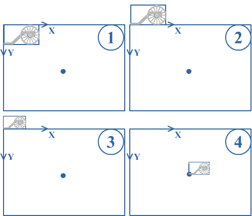
The following image shows the order of operations desired

http://www.riemers.net/images/Tutorials/XNA/Csharp/Series2D/mat1.png

The tutorial says that to create this transformation you use;

Matrix carriageMat = Matrix.CreateTranslation(0, -carriage.Height, 0) * Matrix.CreateScale(playerScaling) 
* Matrix.CreateTranslation(xPos, yPos, 0) * Matrix.Identity;

How could this work if the the order was left to right?

\$\endgroup\$

1 Answer 1

6
\$\begingroup\$

Direct3D and XNA typically use a row-vector convention, meaning that when a vector is multiplied by a matrix, it's interpreted as a single row and multiplied on the left of the matrix. So Vector2 hold = Vector2.Transform(pos1, mat1); means hold = pos1 * mat1. This differs from the column-vector convention in used in OpenGL and in standard mathematical notation, where the vectors go on the right of the matrix, like hold = mat1 * pos1.

This means that matrix operations are applied left to right rather than right to left, so a matrix like mat1 * inv(mat2), when applied to a vector, has the effect of applying mat1 first and then applying inv(mat2).

As for the diagram, it seems to label the transformations in the opposite order to that shown in the code. This is because the tutorial is written in terms of operations on coordinate systems, rather than operations on an object in a single coordinate system. These are two complementary ways of describing the same sequence of transformations:

  1. Reading from right to left, the coordinate system of the carriage is translated, scaled, and translated again as seen in the diagram. Each successive operation occurs relative to the carriage's local coordinates. For instance, the scale takes place relative to the carriage's local origin, and the second translation takes place in the scaled local coordinates.

  2. Reading from left to right, the carriage itself is translated, scaled, and translated again (in the opposite order) with each operation occuring in world coordinates. Here is a modified version of the diagram that shows this: enter image description here

As you can see, the carriage ends up in the same place, but in the second version the coordinate axes do not move and each operation is taking place in world space.

We are still using a row vector convention here, but these are two different but equally valid ways of interpreting the same transformation: going left to right in world space, or going left to right in local space.

\$\endgroup\$
4
  • \$\begingroup\$ Thank you for the answer, but if that's true then how come in the second example the transformations are put in reverse order? \$\endgroup\$
    – Alxander
    Commented Jan 29, 2012 at 21:06
  • \$\begingroup\$ The order of transformations in the code sample makes sense to me: you first translate to put the origin at the lower-left corner (instead of the upper-left), then scale, then translate again to put the carriage wherever it's supposed to be (using its lower-left corner as the reference point). On the diagram you posted, the labels 1, 2, 3, 4 do seem to be in the reverse order. Can you post the link to the tutorial itself? I couldn't find it, but the diagram may make more sense in context. \$\endgroup\$ Commented Jan 29, 2012 at 21:49
  • \$\begingroup\$ Here is the link to the tutorial. riemers.net/eng/Tutorials/XNA/Csharp/Series2D/… The image I posted here down the page \$\endgroup\$
    – Alxander
    Commented Jan 29, 2012 at 22:21
  • \$\begingroup\$ OK, I edited my answer to explain what's going on with the diagram. \$\endgroup\$ Commented Jan 29, 2012 at 22:55

You must log in to answer this question.

Not the answer you're looking for? Browse other questions tagged .