4
\$\begingroup\$

I have been trying to understand how projective texture works; and, even I have been able to achieve the result by following the steps in tutorial, I fail to understand how it works in my mind.

To my understanding, we need to construct a model, a view and a projection matrix for the texture along with a bias matrix which maps to [0, 1].

The usual steps consist of:

  • Calculating the UV within vertex shader by the projection texture's matrix (MVP + Bias matrix).

  • Then, sampling the texture (the smiley face) using the aforementioned UV passed in from vertex.

But what is actually happening within vertex shader and fragment shader?

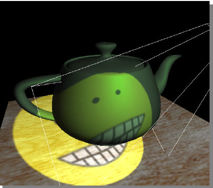
Take the following image, for instance:

enter image description here

Please correct me if I am wrong:

Here, we have a teapot, a background texture and a texture for the projection (the smiley face).

What is happening when the background and the teapot is going through vertex and fragment shader as far as projective texture is concerned?

Some says rather than projecting the texture onto the objects in the scene, we are actually projecting the scene onto the the texture (the smiley face), which I also fail to see.

Again, by using the code found on most tutorial sites I have been able to achieve the result; but my goal is to be able to understand how things work, which I hope someone could offer me a hand here by taking me through the vertex and fragment shader and perhaps post some pictures which could help me to see what is happening in my mind. I have been trying to read several books and online tutorials on this but I have not been successful in understanding it.

Thanks.

\$\endgroup\$

2 Answers 2

3
\$\begingroup\$

When you're projecting a texture, the goal is to take some texture and 'paste' it onto the scene. This is essentially mapping points on the texture to points in the scene, so if we can find a mapping between these coordinate systems we'll have our solution. It's difficult to map from the texture's 2D coordinates to 3D world coordinates, but it turns out to be relatively straightforward to go from 3D world coordinates to 2D texture ones with the help of some usual graphics programming tools.

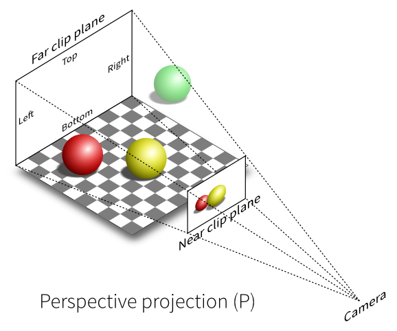
When you use the graphic pipeline normally, you project to the viewport like so:

enter image description here

With texture projection, you're using very similar steps, except instead of a virtual camera, you're creating a view frustum for the texture. You can imagine replacing the near clip plane in the above image with the texture you're projecting, and you can further imagine all of the projected points of the objects in the scene hitting the texture in some place. These places on the texture being hit can also correspond to UV coordinates. The UV coordinate being 'hit' corresponds to the 3D point hitting it in the sense that if you had just 'pasted' the texture onto the scene, that UV coordinate would have hit that 3D point. This is the 3D-to-2D mapping I mentioned earlier.

Like the virtual camera, your texture frustum is defined by a set of MVP matrices. However, after applying them, the projection matrix returns points in clip-space, and after applying perspective division you're in a space from [-1, 1] on your axes. The bias simply adjusts this to [0, 1] so it matches the UV coordinates you want.

I've tried to keep this more conceptual rather than technical because it seems like that's your main problem with it, but let me know if anything can be clarified!

\$\endgroup\$
3
  • \$\begingroup\$ Hi, thanks for response. Unfortunately, I still fail to see how the coordinates are mapped to the coordinates of the projected texture; could you cite an example for that? Second, what would happen if the coordinates don't intersect the texture (because in code, we don't need to check that. So, I wonder how that works)? \$\endgroup\$
    – Unheilig
    Commented Jan 19, 2017 at 21:09
  • \$\begingroup\$ I think, if you have the time to, I would be able to see it better if you could cite an example based on the sequence when the vertex shader is first called, etc etc, to where we shade in the fragment shader with cases when our primitives intersect the projected texture and the case when they do not (in which case when we would simply render our primitive without the projected texture). Thank you so much. \$\endgroup\$
    – Unheilig
    Commented Jan 19, 2017 at 21:10
  • \$\begingroup\$ In addition, you could explain it also in a technical way (if it's needed), because I would be able, also, to understand it without much help (I have been reading the corresponding mathematics because of it). Thanks, again. \$\endgroup\$
    – Unheilig
    Commented Jan 19, 2017 at 21:19
0
\$\begingroup\$

First, let's talk about what "texture mapping" means. The phrase is intended to be taken literally. A texture mapping is the "mapping" from a surface into a texture image. Your surface is defined by vertices, and each vertex has a position.

When it comes to triangle rasterization, the texture mapping is typically created on a per-vertex basis. That is, each vertex has a texture coordinate, which says "for this position in space, get your texture data from this location in the texture." Between a triangle's vertices, the texture coordinates are interpolated, creating a smooth mapping across the planer surface.

But this is merely one particular kind of mapping. There's nothing stopping you from mapping things in another way.


Second, let's talk about what "projection" means. When you render a 3D scene to the screen, you are performing some kind of projection operation. A "projection" is merely the transformation of a position from one dimensionality to another. In our case, from 3D space into a 2D space, namely the screen.

3D rendering involves projection. We have 3D points, and we want to do stuff on a 2D image (namely, the screen). So we have to perform projection: we take the 3D scene and project it onto the 2D image. This operation happens on the vertex positions.

Now, before we do the meat of the projection operation, we generally want to transform the positions into a space relative to the camera. This is done with a 4x4 matrix transform, going from model space to camera space. To do the projection, we apply another 4x4 matrix transform, leading us into 4-dimensional clip-space. Of course, since 4x4 matrices can be composed, we can do this with a single matrix multiply of a composed model-to-clip-space matrix.

At that point, we're done with the vertex shader, because OpenGL or D3D will do the rest of the projection work converting from a 4D clip-space position into a 2D screen-space position. See, this is all hard-coded, and I'm not about to get into the deep details of this process here. But there is one detail I do want to cover.

Perspective projection is not a linear transformation, and a 4x4 matrix can only encode linear transformations. So how do we do projection with a matrix? Because the next step after the VS is dividing the position by the 4th component, the W component. Division by a coordinate is not a linear transform, and it is this division that makes perspective projection non-linear. So we set the W component to the value that needs to be divided in order to do perspective projection.

That division, called the perspective divide, is important. OpenGL/D3D does this step for us automatically when rendering.


So, what is "projection texture mapping"? Well, let's lay out the goal of this process:

We want to compute texture coordinates for our objects so that it appears that a texture is projected over the objects in the scene.

That's the goal. Since we're computing texture coordinates, we are performing "texture mapping". And since we're casting a 2D image over a 3D scene, that sounds like "projection", since we're changing dimensionality.

The trick here is to realize that this projection is no different from the kind of projection you use to render. When you render, you're projecting a portion of a 3D scene into a 2D screen image. When you do projection texture mapping, you're projecting a portion of a 3D scene into a 2D texture image. The only difference is what the destination is. In the former case, you're projecting to do rasterization. In the latter, you're using the post-projection positions as texture coordinates.

But the math is the same.

Indeed, OpenGL even has special Proj texture accessing functions which take that W component, so that you don't have to do the perspective division yourself.

All of the math for doing projection texture mapping is exactly the same as you would use for rendering. Instead of projecting the scene onto a screen-sized area, you're projecting it onto the [0, 1] normalized texture coordinate area. Oh yes, you will use different camera and projection matrices than the one you use for rendering. But the actual math itself, the formulas you use, are all identical.

\$\endgroup\$

You must log in to answer this question.

Not the answer you're looking for? Browse other questions tagged .