6
\$\begingroup\$

I'm using Box2D for a Game Programming course, and I was wondering if it is possible to choose the best shape and size of shape for the rigidbody/fixture for a sprite based on its transparency.

I've tried to build with the idea of new content being easy to add (all data for enemies, terrain, etc. is stored in XML documents). Because of this, there will not be a new class for every enemy. This makes creating the fixture shapes difficult, since it has to be a generic solution but still map realistically to the sprite when the game is being played. The best solution I've come up with so far is to somehow figure out where the majority of the non transparent pixels are in the sprite and build the shape from that.

Does something like this exist? If not, would it be hard to implement?

\$\endgroup\$

2 Answers 2

10
\$\begingroup\$

I tried this. It was hard, but I did it.
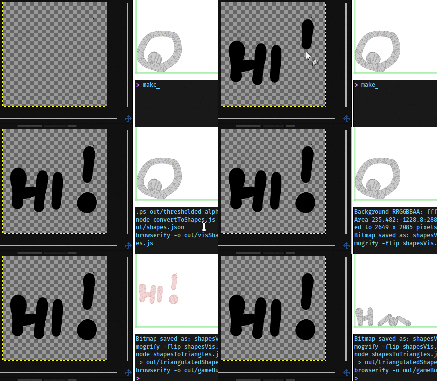
drawing a thing, getting an object

Left is GIMP, top-right is a Box2D debug renderer, bottom-right is a build shell

Code repository for reference

The full code is on github here. It's scattered in a whole lot of files, so it's a bit big to put here. See below for an explanation of the technique.

How?

I used ImageMagick, Potrace, Node.js (with poly2tri.js and simplify-js), and two evenings.

This is possible also with other tools, so I'll go over the steps in a general way:

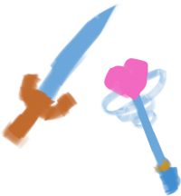
  1. Draw an input image.

    sword and magical girl wand

  2. Extract the alpha channel, because we only care about the shape.
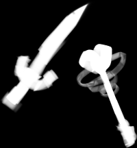
    alpha channel

    convert infile.png -alpha extract outfile.png
    
  3. Threshold the alpha (push everything under 75% opacity to 0% and the rest to 100%)

    thresholded inverted alpha channel

    convert infile.png -threshold 75% -negate outfile.png
    

    This gets rid of the barely visible parts.

    I also negated the image because the next step's Potrace understands black pixels as stuff it should be tracing.

  4. Trace to a vector format.

    With the right options, Potrace outputs an easily readable PostScript file.

    potrace --longcoding --postscript --tight --alphamax=0 \
      --cleartext --output=outfile.ps infile.bmp
    

    I wrote a fairly uninteresting Node.js script to parse the path data out of that and into a JSON data structure.

    I threw the JSON at D3.js to see what the path data looks like. Sure enough…
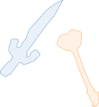
    path data

  5. Simplify and triangulate the path.

    Again a pretty simple Node.js call through simplify, then poly2tri.

  6. Put it in Box2D!

    Create a body for each set of triangles, and add the triangles as fixtures. Remember to handle each triangle's vertices in counter-clockwise order.
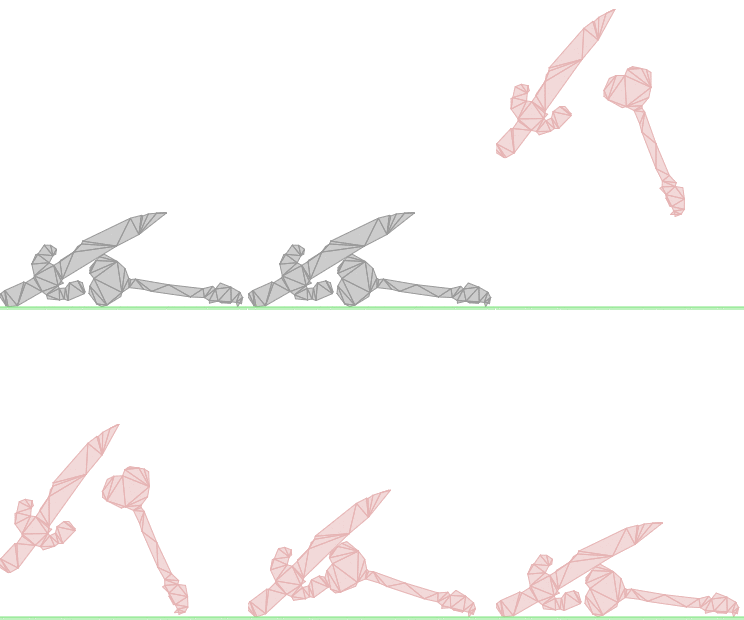
    Box2D bodies!

    Success!

Shapes with holes in them

Sometimes your images have holes, like the One Ring here—
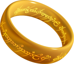
THE RING. No, the other ring.

Thanks user Xander at Wikimedia!

The PostScript path data represents such situations as a sequence of paths (rlineto/moveto-commands followed by a closepath), such that the first path is the enclosing one, and all the rest are holes. That group of paths is then terminated by a fill command.

It looks somewhat like this:

<x> <y> moveto
<x> <y> rlineto
<x> <y> rlineto
[ ... more rlineto ... ]
closepath
<x> <y> moveto
<x> <y> rlineto
<x> <y> rlineto
[ ... more rlineto ... ]
closepath
fill

Here's how it looks when parsed, simplified, and plotted:
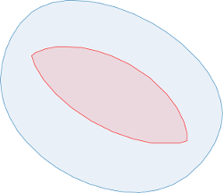
image paths

The blue path is the enclosing one. The red is the hole.

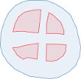
An image might have arbitrarily many holes:
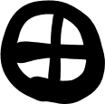
plussed circleplussed circle holes

poly2tri has methods that allow you to add holes to the generated path, as any other Delaunay triangulation library worth its salt should.

And finally, the ring in Box2D for good measure:
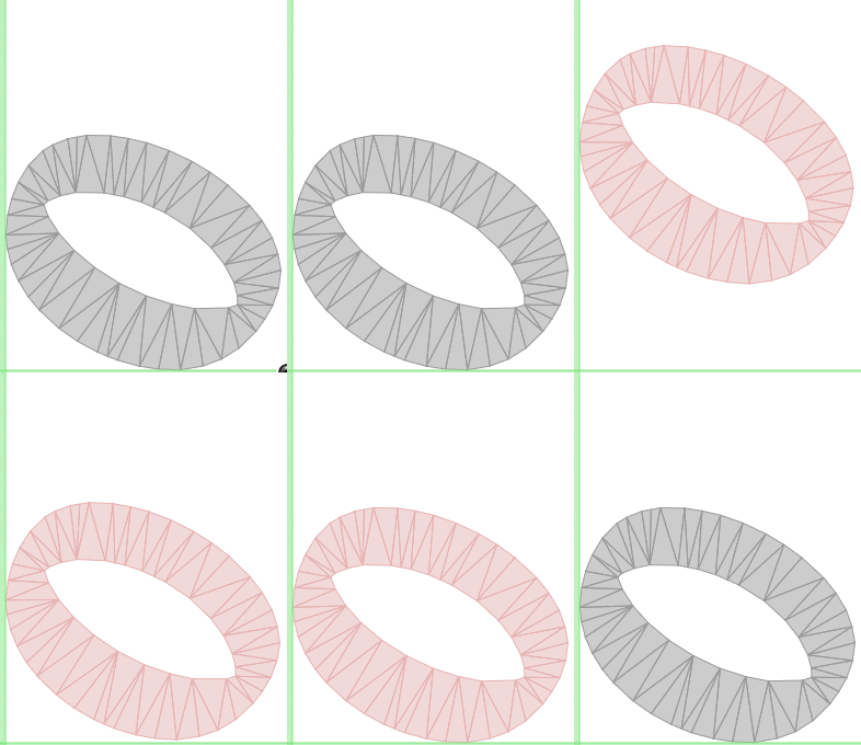
The One Ring in Box2D

\$\endgroup\$
6
  • \$\begingroup\$ I noticed you are using make. That means it's unix-only, right? \$\endgroup\$ Commented Feb 2, 2016 at 0:41
  • \$\begingroup\$ @NauticalMile I tested this in Linux, but all of the programs I used are also available for Windows, including make. \$\endgroup\$
    – Anko
    Commented Feb 2, 2016 at 12:49
  • \$\begingroup\$ cool. I didn't know. I'll test it tonight on my Windows machine. \$\endgroup\$ Commented Feb 2, 2016 at 15:32
  • \$\begingroup\$ @NauticalMile I have no Windows machine handy to test on, but I'd be very interested in the results: do ask if you get stuck. The code could definitely use some more comments. :) \$\endgroup\$
    – Anko
    Commented Feb 2, 2016 at 15:48
  • 1
    \$\begingroup\$ That's awesome! We ended up having to make some assumptions and left things kinda boxy, but that is very impressive! Thanks for the hard work! Not sure when/if I'll have a chance to implement this (that class ended already), but I will accept this and hope that someone else will be able to benefit from this answer and the one that @NauticalMile provided. \$\endgroup\$
    – vdwtanner
    Commented Feb 2, 2016 at 21:30
2
\$\begingroup\$

R.U.B.E. does this. The feature was included with the addition of samplers since v1.6.0. This tutorial video gives a description of how it can be done.

To test, I used Anko's and Xander's images for comparison.

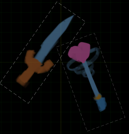
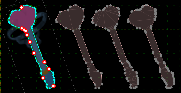
First I imported the image of the sword and heart wand into RUBE (I'm on v1.7.0) and created some samplers (shown by dashed outlines) over them.

sword and heart wand

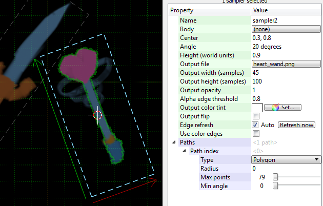
Once this is done the threshold alpha value can be set in the properties window for any selected samplers.

sampler properties

As seen above, a green outline appears showing the predicted outline of the shape. Then by using a special edit mode to select key points on your fixture outline. Depending on where the key points are, you can increase the density of fixture vertices in different areas of the outline. I've shown a couple of fixtures generated by RUBE when the control points are placed in different areas:

control points

There is also a shortcut to create a new body from an image with a single shape (see the video for details).

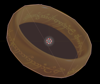
It does not currently handle holes properly:

enter image description here

Summary

Here is a comparison with Anko's solution:

+---------------+----------------------------+-------------------------+
|               | Anko's image-to-box2d-body |         R.U.B.E         |
+---------------+----------------------------+-------------------------+
| Platform      | Linux, Mac, and Windows    | Linux, Mac, and Windows |
| GUI           | No                         | Yes                     |
| Price         | Free                       | ~$35 USD                |
| Open-source   | Yes                        | No                      |
| Handles Holes | Yes                        | No                      |
| Dependencies  | Yes (See github page)      | No                      |
+---------------+----------------------------+-------------------------+
\$\endgroup\$
1
  • \$\begingroup\$ Thanks for the additional option! This looks like it could be very helpful. \$\endgroup\$
    – vdwtanner
    Commented Feb 2, 2016 at 21:31

You must log in to answer this question.

Not the answer you're looking for? Browse other questions tagged .