4
\$\begingroup\$

I am currently working on a curve implementation for use in Unity which includes an editor:
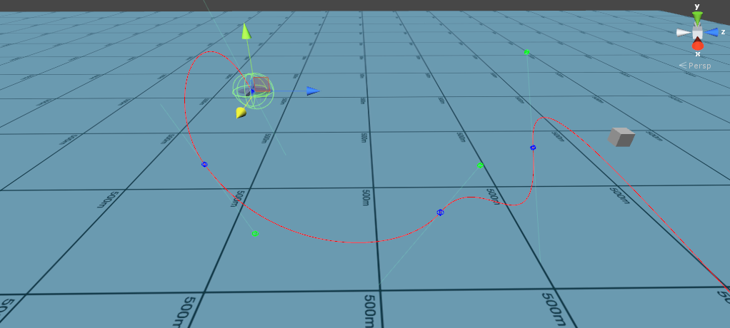
screenshot

The aim is to get an object to follow the path represented by the curve at a constant velocity. Currently you can place nodes in the curve and modify the weights of each node via handles to control the curve segments between nodes. The curve implementation is a standard Bezier curve.

It works as described except that sometimes the rotation of the object along the path is not great. For instance doing a vertical loop can cause the object to suddenly flip over at certain points. I am currently setting the rotation of the object as follows:

transform.LookAt(bezier(waypoints, handles, lookAhead));

This is computing the point in the curve slightly ahead of the current point and setting the object to "look at" that point. The pitch and yaw of the object will therefore be correct but the roll cannot be easily controlled.

I am currently trying to implement a way to control the roll as the object travels along the path but my maths skills are failing me once again. In the editor I am thinking of placing "roll" nodes along the path which represent the desired roll angle of the object when it reaches that node and interpolating between these nodes for the points in between. My questions are as follows:

  1. How would you determine the yaw and pitch manually at each point? My objects are airplanes so they will always be facing "forward".

  2. How would you know the direction to turn towards to get to the next nodes roll angle? It could be anticlockwise or clockwise I assume. Would I need to also add a control to say which way to turn?

  3. How would I determine what is "up" to orientate myself when controlling the roll angle of the objects along the path?

EDIT:

Example: https://www.youtube.com/watch?v=0BHGoKOIQa0&feature=youtu.be

The linked youtube video shows the problem I am experiencing with using

 transform.LookAt(bezier(waypoints, handles, lookAhead));

alone to control the rotation Quaternion. Watch the plane object rotate when looping vertically. The box sticking out is on the top of the plane object.

When the object reaches the point when it should be "upside down" in the loop it spins quickly to be the facing upwards again. If I can make it so that the up vector of the object along the path follows the "natural" rotation along the curve I can then apply Quaternion control points to properly control rotation. Sorry if this is not entirely clear, I don't know the proper terminology for a lot of this stuff.

\$\endgroup\$
2
  • \$\begingroup\$ Very quick though: I would need to see more from your code, but by your video it seems to me that the plane is accurately following the path that was draw. Maybe your problem is not in the math for the rotation, but at the bezier calculation (i.e. you actually wanted it to describe a path slightly different from the one it is - for instance inverting the position of the flying plane) \$\endgroup\$
    – MAnd
    Commented Nov 16, 2015 at 10:02
  • \$\begingroup\$ You might want to see how blender does their (3d-enabled) beziers. Their curves have an "up" that varies along the line and some sort of twist value at each control point that determines how many revolutions "up" makes between two nodes. \$\endgroup\$
    – Weaver
    Commented Mar 18, 2016 at 6:49

2 Answers 2

2
\$\begingroup\$

Edit: New Solution

Edit: I have found a solution that works for me (as mentioned in the comments):

Use an iterative approach. Start with a reference frame at the start of the bezier. Then, for each new point, use the orientation of the previous frame to orient the next one:

forwardOnCurve = DeriveCubic(p[0], p[1], p[2], p[3], Mathf.Clamp01(t)).normalized;
normalOnCurve = Vector3.Cross(forwardOnCurve, Vector3.Cross(normalOnCurve, forwardOnCurve)).normalized;

As you can see, I calculate the right vector from the new forwards vector and the previous normal. Then I calculate the new normal.

The problem with this approach is that while it is locally continuous, it ignores the orientation of all control points but the first.

To solve this, I rotate all points along the forwards vector between each control point, linearly interpolating the error angle to be correctly oriented at the next control point. Also, I treat each segment individually, always starting correctly oriented at each control point.

What should be the starting normal at each control point? Well you want to decide that for yourself, right? I use the control handles in addition to a normal for each control point. This way, the user can rotate the bezier at each control point to point the way they want.

The correction looks something like this:

segmentLength += Vector3.Distance(previousPointOnCurve, p[3]);
lineLength += segmentLength;

forwardOnCurve = DeriveCubic(p[0], p[1], p[2], p[3], 1).normalized;
normalOnCurve = Vector3.Cross(forwardOnCurve, Vector3.Cross(normalOnCurve, forwardOnCurve)).normalized;
float angleError = Vector3.SignedAngle(normalOnCurve, _normals[segment + 1], forwardOnCurve);

// Iterate over evenly spaced points in this segment, and gradually correct angle error
float tStep = spacing / segmentLength;
float tStart = Vector3.Distance(esp[startIndex].position, p[0]) / segmentLength;
for (int i = startIndex; i < endIndexExclusive; ++i)
{
    float t_ = (i - startIndex) * tStep + tStart;
    // TODO: make weight non-linear, depending on handle lengths
    float correction = t_ * angleError;
    esp[i].normal = Quaternion.AngleAxis(correction, esp[i].forward) * esp[i].normal;
}

The full code is this: https://pastebin.com/t5LFLhL9

This can also be found in context in my unity package called "MB Road System"

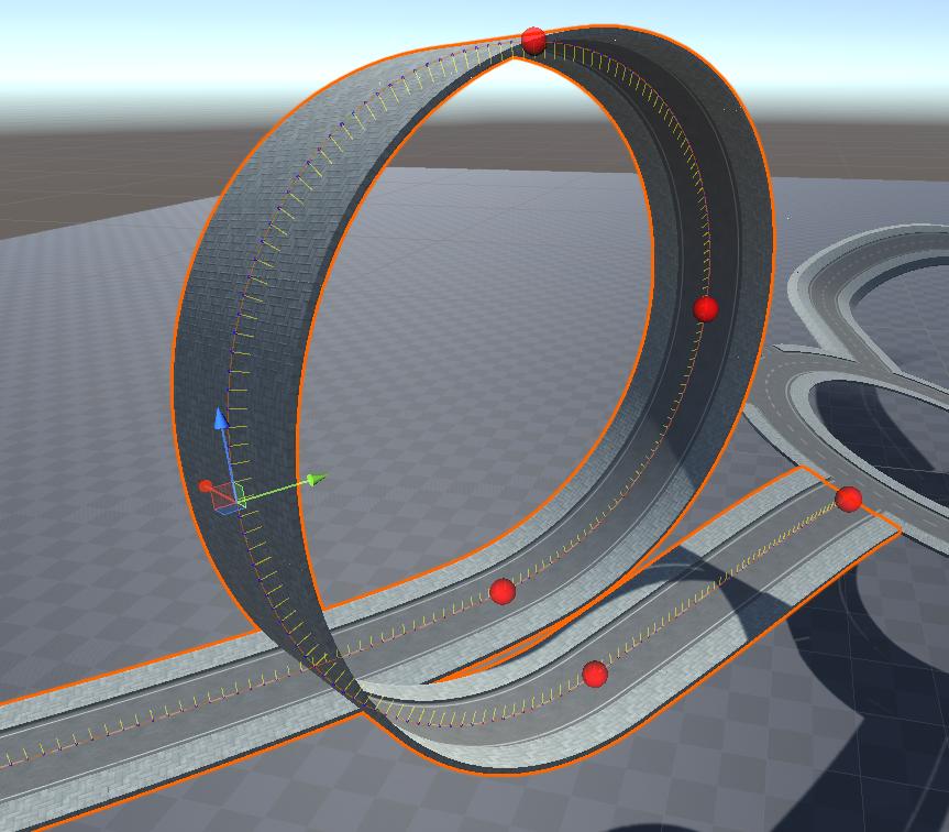
Screenshot

Road using the bezier editor

As you can see, this works vertically too now. The only problem is that you have to calculate the entire curve, you can't just sample the normal of the curve at any point along the bezier without calculating the entire array of points. However, since I assume your curve is not updated during run-time, this shouldn't be a problem. I personally recommend updating these points asynchronously while storing the current array in a variable, so that it can update at a slower frequency than the main loop. This is, I think, a good compromise.

My Old solution

I'm looking into this as well. I only have a solution that works for beziers that are somewhat horizontal, the closer they get to vertical, the less it works.

I'm essentially converting the local up vector into an angle, interpolating that, and turning it back into an up vector.

Conversion from normal to angle:

You use the vector along the bezier (p[t + 1] - p[t]) and take the cross product with the worlds up vector. That gives you the right vector relative to the path. Then you take the cross product between that and the local forward vector, and that gives you a vector that points 90° to the bezier, upwards. You can then measure the angle of the transforms up vector to that, and you should get the local roll.

This roll is then interpolated along the path.

Generating a normal from the local angle works similarly.

This is the code that I wrote:

public static float AngleFromNormal(Vector3 forward, Vector3 normal)
{
    Vector3 right = Vector3.Cross(Vector3.up, forward).normalized;
    Vector3 up = Vector3.Cross(forward, right).normalized;
    return Vector3.SignedAngle(normal, up, forward);
}

public static Vector3 NormalFromAngle(Vector3 forward, float angle)
{
    Vector3 right = Vector3.Cross(Vector3.up, forward).normalized;
    Vector3 up = Vector3.Cross(forward, right).normalized;
    return Quaternion.AngleAxis(-angle, forward) * up;
}

Now, as I said, this only works if the path is somewhat horizontal, as it relies on the cross product of the forward vector and Vector3.up to return a vector that is long enough to avoid floating point error or division by 0 (when the vector is normalized)

I personally used it for a RoadSystem that lets you edit roads, connect them to intersections, and it also generates a graph for pathfinding, and can then generate a line from your position to the goal. In that use case, this approach works well enough, as roads don't really go up vertically.

\$\endgroup\$
3
  • 1
    \$\begingroup\$ You can store your reference up vector from one sample point to the next, to avoid nasty behaviour when the Bézier turns vertical. \$\endgroup\$
    – DMGregory
    Commented Mar 4, 2021 at 14:14
  • \$\begingroup\$ Ah yeah that makes sense! I just need to keep in mind that the calculation of the next vector needs to use an angle relative to the last one (so instead of linearly interpolating the angle, we just use the relative roll between points). I'll definitely give that a shot! \$\endgroup\$
    – user959902
    Commented Mar 5, 2021 at 20:20
  • \$\begingroup\$ P.S.: For animating something along the path, just use Time.DeltaTime to linearly interpolate between the evenly spaced points. Since the distance between them is constant, this is pretty simple. \$\endgroup\$
    – user959902
    Commented Dec 16, 2021 at 16:38
-1
\$\begingroup\$

You could just stare the roll value before each

transform.LookAt(bezier(waypoints, handles, lookAhead));

And then just adjust the roll value as you want in a separate algorithm and then reassign it to the airplane's roll. The Euler roll 0 is always straight and 360 = 0.

So the questions drictly:

  1. Use a quaternion and do a slerp to rotate to that orientation.

  2. Roll values loop at 360 so 270 = -90. You could just test if the value is larger than 180 then the other direction is faster and then do a lerp or some control algorithm.

  3. Roll=0 is always up.

If this did not help pleas clarify what is unclear an I will clarify.

EDIT: One way to work around this is to store the rotation and whenever the yaw has a difference (remember the 360 looping so 5 to 355 is only 10) from the previous frame is greater than 170 (the yaw will flip 180 when the flip ocur) degreas just add 180 to the roll value.

\$\endgroup\$
1
  • \$\begingroup\$ Thanks for replying. I think I sort of understand what you are saying. The problem I am experiencing now is to properly calculate what the starting UP vector should be at every point on the curve before I apply the roll modifications. I have added a link to a youtube video in my original qs which illustrates this problem. \$\endgroup\$
    – Jkh2
    Commented Feb 15, 2015 at 18:07

You must log in to answer this question.

Not the answer you're looking for? Browse other questions tagged .