0
\$\begingroup\$

I made a post yesterday to see if anyone could understand my problem.

However I did not receive much guidance, probably because my question was not clear.

I have worked on it a little more and discovered the actual issue and now have a clearer picture of what is causing the problem.

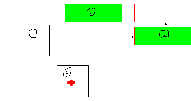
As you can see from the image, the boxes are projected correctly along their appropriate axis (all components labeled 1 are from the main white box 1 and vice versa). Image 1

The problem comes when the box is rotated. (See image 2). Box 1 has been rotated but the corner (projection?) in green clearly does not match the shape of the rotated box 1 and is much much closer to box 2 than it should be. The axis projections have changed and axis 1 is on the far left but axis 3 has gone?

Problem

THE CODE CAN BE SEEN ON MY PREVIOUS POST Separating Axis Theorem Issue

Thank you! ;D

\$\endgroup\$
7
  • \$\begingroup\$ Your images are confusing what are the green polygons compared to the white ones ? Are they in the same space ? Do you project green boxes on axes rather than white boxes and why ? \$\endgroup\$
    – Lærne
    Commented Apr 3, 2014 at 12:26
  • \$\begingroup\$ The Green boxes show the corners of the white boxes as they are seen by the axis. The green boxes show where the corners are when the transformation has been applied. \$\endgroup\$
    – Nick
    Commented Apr 3, 2014 at 12:28
  • \$\begingroup\$ I don't understand what is your transformation. In the axis projection theorem, you must project your boxes onto a line, which means that the final result is a line segment. Again, what is your transformation to obtain green polygons, and what do you mean by « seen by the axis ». Your previous code is too large, just give me simple formulas. \$\endgroup\$
    – Lærne
    Commented Apr 3, 2014 at 13:42
  • \$\begingroup\$ When I say transformation I just meant rotating the box. In the algorithm that I am using, you calculate each corner and then Corner 0 is always chosen as the base of the projection lines. The green polygons are the corners[] that represents the White box, so that is how the algorithm actually see's the boxs. \$\endgroup\$
    – Nick
    Commented Apr 3, 2014 at 13:55
  • \$\begingroup\$ I'll try to record a clip of what is happening so that you can clearly see what is going on. \$\endgroup\$
    – Nick
    Commented Apr 3, 2014 at 14:03

1 Answer 1

1
\$\begingroup\$

The problem with your image is that the green box is first rotated then stretched. With no rotation, this gives the correct rectangle, but then it fails.

Anyway, I don't think you understood clearly how the algorithm works. The algorithm consists to check whether the projection on an axis of the two shapes intersects, for each axis of a nicely selected set of axes. The set of axis consist of the line going through the normal at each face, i.e. a line perpendicular to each face. Luckily in the case of boxes, it implies only two lines per shapes since sides are parallel by twos.

In the following picture, there are two boxes, in yellow and orange. Every axis is depicted by a black line.

One orange box and one yellow box both with their normal axes

Consider the projection on the slightly dipping axis. Its projection in the orange segment of the line. The segment was obtained by orthogonally projecting the vertices of the orange box (i.e. its corners) onto the line. They are obtained by intersecting the axis with the blue dashed lines, each one of which is a perpendicular of the axis going through a rectangle vertex.

The projection of the yellow box on one of its axis is trivial ; it is the dark yellow segment of the axis. You then have to check whether the two segments intersects. If they don't, the box don't intersect either, if they do, you have to check along another axis. If on each axis, the projection of the boxes intersect, then the two shapes intersects.

There's an optimization doable here : check that the projected vertices are either all on the left of the left side of the yellow box or all on the right of its right side. If they do, the projected segments do not intersect. Else they do intersect.


Note : Since each shapes has only two axes those axis may serve as a reference system for the plane. Consider the system generated by the yellow box, I shall call it the “yellow system”. Then each segments obtained by projecting the orange box on each yellow axis corresponds to the sides the axis-aligned bounding box (AABB) of the orange box in the yellow system. In the picture that I remind below, this AABB is reprensented by a dotted rectangle boundary. See how the projected segment correspond to a translation of some sides of the AABB.

The dotted green box is the AABB of the orange box in the yellow's box reference system

Maybe building this AABB was what you were trying to compute. But to compute it nicely, you have to compute the projected segment first anyway, so there is no gain to explicity compute AABBs. In any case, I can't understand how such an AABB can be a rectangle when using two squares with the same orientation.
\$\endgroup\$

You must log in to answer this question.

Not the answer you're looking for? Browse other questions tagged .