1
\$\begingroup\$

Im trying to make a tool for skinning 3D models, and as part of that, I need to show faces wireframed, making use of the geometry shader stage.

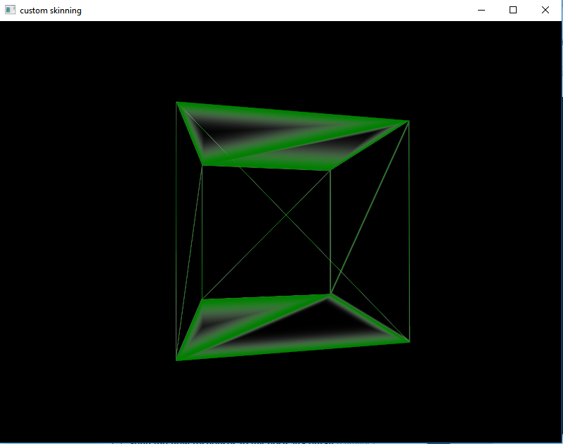
Im following the approach suggested here and here. My problem however, is that it ends up looking like this:

lines too thick!

Where some of the lines get thicker when the faces are oriented in a specific way. This is my geometry shader: (The vertex shader just passes vertices, so theres no need to show it)

#version 400

layout(triangles) in;
layout(triangle_strip, max_vertices = 3) out;

noperspective out vec3 gDist;

void main()
{
//800,600=window size(make uniform later)
vec2 p0 = vec2(800,600) * gl_in[0].gl_Position.xy/gl_in[0].gl_Position.w;
vec2 p1 = vec2(800,600) * gl_in[1].gl_Position.xy/gl_in[0].gl_Position.w;
vec2 p2 = vec2(800,600) * gl_in[2].gl_Position.xy/gl_in[0].gl_Position.w;

vec2 v0=p2-p1;
vec2 v1=p2-p0;
vec2 v2=p1-p2;
float area = abs(v1.x*v2.y - v1.y * v2.x);

gDist = vec3(area/length(v0),0,0);
gl_Position = gl_in[0].gl_Position;
EmitVertex();

gDist = vec3(0,area/length(v1),0);
gl_Position = gl_in[1].gl_Position;
EmitVertex();

gDist = vec3(0,0,area/length(v2));
gl_Position = gl_in[2].gl_Position;
EmitVertex();

EndPrimitive();
}

and frag shader:

#version 400

noperspective in vec3 gDist;

const vec4 wire_color = vec4(0.0,0.5,0.0,1);
const vec4 fill_color = vec4(1,1,1,0);

void main()
{
float d = min(gDist[0],min(gDist[1],gDist[2]));
float i = exp2(-2*d*d);

gl_FragColor = i * wire_color + (1.0 - i) * fill_color;
}

So what am I doing wrong here? I feel like im missing something. Is anyone familiar with this?

\$\endgroup\$

1 Answer 1

1
\$\begingroup\$

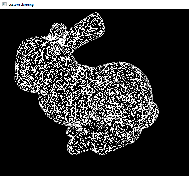
I suspect the main problem with my original attempt was thinking in 2D only. Before I was calculating the edge distance as it appears onscreen, when I should be calculating the value with 3D space in mind. The solution I reach is not the same outlined here on page 216, but it still seems to be correct. It looks like this using the Stanford bunny:

enter image description here

As before, the vertex shader doesn't do anything for now, other than pass vertices after being put in projectionviewmodel space, so I wont bother posting it.

In the geometry shader there are some differences however, notice how I don't divide by .w and just extract the values directly:

#version 400

layout(triangles) in;
layout(triangle_strip, max_vertices = 3) out;

in vec2 fUV[]; //uv coordinates
out vec2 gUV;

noperspective out vec3 GEdgeDistance;

void main()
{
    float a = length(gl_in[1].gl_Position.xyz - gl_in[2].gl_Position.xyz);
    float b = length(gl_in[2].gl_Position.xyz - gl_in[0].gl_Position.xyz);
    float c = length(gl_in[1].gl_Position.xyz - gl_in[0].gl_Position.xyz);

    float alpha = acos( (b*b + c*c - a*a) / (2.0*b*c) );
    float beta = acos( (a*a + c*c - b*b) / (2.0*a*c) );
    float ha = abs( c * sin( beta ) );
    float hb = abs( c * sin( alpha ) );
    float hc = abs( b * sin( alpha ) );

    gUV=fUV[0];
    GEdgeDistance = vec3( ha, 0, 0 );
    gl_Position = gl_in[0].gl_Position;
    EmitVertex();

    gUV=fUV[1];
    GEdgeDistance = vec3( 0, hb, 0 );
    gl_Position = gl_in[1].gl_Position;
    EmitVertex();

    gUV=fUV[2];
    GEdgeDistance = vec3( 0, 0, hc );
    gl_Position = gl_in[2].gl_Position;
    EmitVertex();
}

In the frag shader there are some options to how you want to display the final model, perhaps only parts of it wireframed, perhaps with phong shaders etc, so Im only posting a basic frag shader that leaves everything to the inquisitive:

#version 400

in vec2 gUV;

uniform sampler2D png_tex;
uniform float wire_thickness;

noperspective in vec3 GEdgeDistance;

void main()
{
//base fragment color off of which edge is closest
float distance = min(GEdgeDistance[0],min(GEdgeDistance[1],GEdgeDistance[2]));

//draw the each side with different color, displaying the barymetric concept
//if (distance==GEdgeDistance[0])gl_FragColor=vec4(0.52,0,0,1);
//else if (distance==GEdgeDistance[1])gl_FragColor=vec4(0,0.52,0,1);
//else if (distance==GEdgeDistance[2])gl_FragColor=vec4(0,0,0.52,1);

if (distance<wire_thickness)gl_FragColor=vec4(1); //draw fragment if close to edge
else if (distance>=wire_thickness)discard; //discard if not
}

The main issue now is whether the geometry shader is as efficient as it could be. I'm certain there is a way to do this making use of dot products and less costly operations than sin/cos/tan trigonometry.

Further reading:

NVIDIA: white paper - solid wireframe,

Two Methods for Antialiased Wireframe Drawing with Hidden Line Removal

David Wolff - OpenGL 4.0 Shading Language Cookbook

\$\endgroup\$

You must log in to answer this question.

Not the answer you're looking for? Browse other questions tagged .